Development of: Hand gauges for inspection of switch points to prevent wheel climb
Written by Jenifer Nunez, assistant editor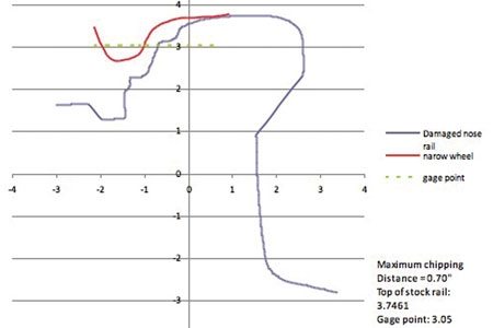
Researchers look to techniques established abroad to develop improved tools for switch inspection in order to reduce wheel climb derailments.
{besps}July14_switch{/besps} {besps_c}0|1switch.jpg|AAR 1B narrow flange wheel profile on damaged switch point of Number 10 turnout.{/besps_c} {besps_c}0|2switch.jpg|Chipped Point Gauge.{/besps_c} {besps_c}0|3switch.jpg|Chipped Point Gauge in field .{/besps_c} {besps_c}0|4switch.jpg|New AAR 1B Wheel Profile Gauge in bottom measurement position. Severely worn AAR 1B wheel prfile in top (inactive) position.{/besps_c} {besps_c}0|5switch.jpg|Contact below 60-degree mark on new AAR 1B Wheel Flange Gauge.{/besps_c} {besps_c}0|6switch.jpg|Adjustable 80-degree notched gauge (top) and 75-degree gauge (bottom).{/besps_c} {besps_c}0|7switch.jpg|75-degree worn wheel gauge with unsage contact.{/besps_c} {besps_c}0|8switch.jpg|Gage Face Wear Angle Gauge.{/besps_c}
by Dr. Allan M. Zarembski PE, FASME Hon. Mbr. AREMA, research professor and director of Railroad Engineering and Safety Program, University of Delaware and Brad Kerchof, director Research & Tests, Norfolk Southern Railway
Researchers look to techniques established abroad to develop improved tools for switch inspection in order to reduce wheel climb derailments.
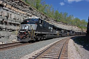
Wheel climb in switches remains a frequent cause of derailments on freight, passenger and transit rail operations in the United States. While some causes are relatively straight forward, such as over speed entering or leaving the switch, or a broken point, most wheel climb derailments are a combination of poor or degraded switch point condition and a worn or degraded wheel profile. While some guidelines and standards for switch condition exist, there are currently no easy-to-use gauges available for track inspectors to identify switch points that have the potential for allowing wheel climb.
A recent project sponsored by the National Academy of Sciences Ideas Deserving Exploratory Analysis (IDEA) Program looked at improved inspection tools that can be used to reduce wheel climb derailments at switch points.1 This project started by looking at international inspection practices and the potential application of these practices for U.S freight and passenger railways. The project identified measurement tools for inspection of switch points used on a number of European railways, including Network Rail (UK) and SBB (Swiss Federal Railways).2 Noting that European railroad conditions and operating parameters differed noticeably from U.S. practices, the IDEA program and its expert panel looked at identifying those inspection gauges that could be modified and adapted for U.S. conditions to include expected lateral (L), vertical (V) and L/V force levels and the associated potential for wheel climb in the switch point areas.
The study team identified four potential wheel climb mechanisms that are of particular concern to U.S. railways. They included:
- Chipped or damaged switch points.
- Poor wheel/rail contact through the point for new or moderately worn wheel profile.
- Excessive gauge face wear of the switch point.
- Severely worn wheels.
To measure these four mechanisms, a series of hand gauges were developed, fabricated3 and field-tested in yards of a major Class 1 railroad.
For the chipped or damaged switch point, European gauges were modified to reflect U.S. wheel and switch point geometry. This modification was based on a series of analyses performed using the standard AAR 1B wheel profiles (both narrow and wide flange) and measured switch point profiles. This included analysis of the location of the gauge point of wheel (where radius reverses on wheel flange), where there is the greatest potential for wheel climb. As illustrated in Figure 1, for the AAR 1B narrow flange wheel, the analysis determined that the distance from top of stock rail to the point of potential wheel climb should be approximately 0.70 inches and that the gauge face angle should be 70 degrees.
The shape of the Chipped Point Gauge is shown in Figure 2. Figure 3 shows how this gauge is used in the field; note that it is mounted on a gauge-width rod to maintain a correct orientation.
The second set of hand gauges addressed the issue of improper wheel contact that could result in the flange climbing the switch point. Here too, European gauges were modified to reflect U.S. wheel profiles, including a new AAR 1B profile (the bottom gauge in Figure 4), a moderately worn AAR 1B profile and a severely worn AAR 1B profile (the top gauge in Figure 4).
The new AAR 1B wheel profile was evaluated in a yard environment where it was determined that switch point contact below the 60-degree mark indicates that the potential for wheel climb exists and remedial action may be necessary (Figure 5). This gauge was judged to be a helpful aid to inspection. The severely worn AAR 1B profile likewise represents a condition that contributes to derailments; however, analysis of the mechanisms of wheel climb suggested that the 60-degree check is not an effective indicator of potential wheel climb for this severely worn profile.
Based on the results of the field tests with the severely worn profile gauges, the Norfolk Southern members of the team developed a gauge that simulates contact of a worn (vertical) wheel flange. This gauge, referred to here as Severe Profile Gauge (SP Gauge), has an angled gauge face with the measuring section adjustable vertically, which duplicates worn wheel/switch point contact, no matter what the height of the switch point is relative to the stock rail.
The team looked at several different gauge face angles and finally selected 80 degrees and 75 degrees for further testing (see Figure 6). The 80-degree gauge face angle was judged to be too steep, but not by much (the gauge face angle of a new switch point for NS standard plan is 78 degrees). To address this, the team added a small square notch to the bottom corner of the 80-degree gauge, to make the gauge less likely to fail a good switch point. A “pass” edge and a “fail” edge were marked on the notch. However, it was judged that this gauge is hard to see (the notch is very small), and too lenient (allows acceptance of potentially failing point). The gauge with a 75-degree gauge face angle performed better, condemning fewer good switch points. Figure 7 shows the application of the 75-degree SP Gauge on a switch point in the yard test.
While both of the adjustable SP gauges were judged to be useful for identifying a potential for a wheel climb derailment, there was still some concern regarding these as “final products.” The 75-degree gauge was deemed to be more conservative in that it may condemn marginally good points. The 80-degree notched gauge was considered non-conservative in that it may pass some marginally bad points. In addition, therewas concern that the gauge position – tight against the stock rail – did not accurately reflect wheel flange tracking position on the bent stock rail side of the switch.
The fourth gauge looked at wheel climb at a switch point with a significant gauge face wear angle. Studies have indicated that development of a significant angle between the gauge face and vertical creates the potential for a wheel to climb, particularly in an unlubricated condition with a high coefficient of friction.5 For example, for a very dry condition (corresponding to a coefficient of friction of 0.5), a 28-degree gauge face wear angle requires only an L/V level of 0.70 to initiate wheel climb.
Noting that the traditional Nadal wheel climb threshold is 0.8 and that the majority of the measured maximum L/V ratio values are of the order of 0.8 or less, a wear limit on the order of 26 degrees to 33 degrees is appropriate. This is consistent with the maintenance values adapted by several U.S. and international railway systems, who have defined gauge face wear limit values between 26 degrees and 32 degrees, based on the anticipated (or measured) levels of loading and standards for lubrication.
The Gage Face Wear Angle Gauge, illustrated in Figure 8, has a 32-degree gauge face angle and specifically addresses the potential for wheel climb under high L/V conditions.
Thus, the conclusions of the IDEA study, which involved three sets of field tests, found that the four identified gauges were useful, effective and a helpful aid to inspection:
- The Chipped Point (CP2) Gauge addresses chipped or damaged switch points.
- The AAR1B gauge is the U.S. version of the European wheel profile gauge. Switch point contact below the 60-degree mark identifies an undesirable wheel/rail contact condition that could lead to wheel climb.
- The Severe Profile Gauge, based on a severely worn AAR 1B profile, gives an indication of potential wheel climb by a severely worn wheel. While both the 80-degree notched gauge and the 75-degree gauge were judged to be useful in identifying high risk switch points, they still require a degree of judgment. Additional development work is required before this gauge will be accepted as a go/no go inspection tool.
- The Gage Face Angle Gauge with a 32-degree angle is used as a check for gauge face angle and the potential for wheel climb, particularly for high L/V conditions.
The IDEA study team concluded that these four gauges show potential as useable field deployable measuring tools to inspect switch points, an area in which there is a noticeable “gap” in current measuring tools and practices. The gauges now need to make the move from research project to field validation and implementation.
References
1. National Academy of Sciences, Ideas Deserving Exploratory Analysis, Transportation Safety Technology Project SAFETY-23 Reducing Wheel Climb at Switch Points to Reduce Derailments.
2. Zarembski, A. M. November 2013. “Improving Inspection of Turnouts.” Railway Track & Structures, 24-27, Chicago, Ill.
3. Norfolk Southern Railroad Research and Tests Department fabricated the gauges used in these field tests.
4. Switch profile provided by Harsco Rail’s Automated Switch Inspection Vehicle (ASIV).
5. Zarembski, A. M. March 1996. “Development of Rail Gage Face Angle Standards to Prevent Wheel Climb Derailments.” American Railway Engineering Association Annual Technical Conference, Chicago, Ill.
Editor’s note on gauge versus gage: RT&S uses the spelling of gauge with a “u” in all instances with the exception of proper names, such as the gauge name in Figure 8 and non-RT&S references.
RELATED ARTICLES