Rail Flaw Testing Gets Faster, Smarter, Better
Written by Bob Tuzik, contributor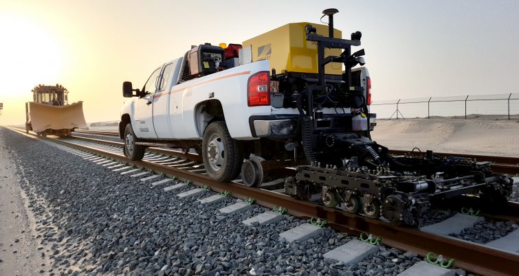
Sperry’s Adaptive Testing System (ATS) is a smaller, easily deployable system that allows for high-frequency rail flaw detection system that attaches to existing hi-rail equipment.
Continuous, non-stop testing is moving testing accuracy and efficiency forward. Is machine learning or artificial Intelligence the next wave?
Year over year, rail breaks caused by internal defects represent a, if not the, leading cause of track-related derailments in North America. Year over year, Class 1, regional, passenger and rail transit systems submit to ultrasonic (UT) inspection to find and remove internal defects before a heavy train, a high-impact wheel load, or a cold snap finds them and leaves the rail, and sometimes trains, in pieces on the ground.
The good news is that UT inspection has proven effective at finding on the order of 90 percent of the internal defects in rail before something catastrophic happens. The bad news is that due to limitations of the technology, the other 10 percent remain out there, lurking in the rail base, the mid-web and web/head fillet of the rail where the existing technology cannot “see,” and under shells and other rail surface anomalies that mask their presence and prevent detection by conventional UT inspection systems.
UT rail flaw detection dates to 1928, when Dr. Elmer Sperry introduced the world’s first non-destructive method of detecting internal rail defects. The approach, as described by the TTCI engineers Matthew Witte and Anish Poudel in the TTCI’s Technology Digest (TD-16-030), uses transducers housed in the roller search units (RSUs) of a detector car to emit ultrasonic waves into the rail then “listen” for the echo of reflected energy that occurs at internal discontinuities and the surfaces of the rail. The amount of reflected sound energy is displayed on a time chart, which provides information about the features that reflect the sound. A trained operator learns to discern the difference between defects and normal features, such as bolt holes and welds.
The biggest problem in testing today is the inability to get full coverage of the rail.
“Several factors limit the detection capability of conventional ultrasonic systems. Foremost is the directionality of the ultrasonic beam. Ultrasonic waves are direction-specific, which works both for and against the inspection objectives. The benefit is that measurements are accurate in a given direction; the drawback is that the directions must be selected and controlled. As a result, there is no broad coverage from a conventional, single-crystal probe. Conventional ultrasonic inspection systems use several probes pointed in specific directions to inspect certain volumes of the rail material. The inspection angles are pre-determined and fixed by the hardware; this inherently limits the area of the head that gets inspected. Only ‘high likelihood’ areas are inspected for defects.”
As one railroader put it, the biggest problem in testing today is the inability to get full coverage of the rail. On northern railroads, for example, rail breaks occur under high tensile stresses induced by low temperatures in the winter months. Investigations into broken rails have shown that the defects found at rail breaks are essentially undetectable with the current technology.
The number of service failures caused by detail fractures, for example, are outweighed by the number of breaks that occur in the base, the web/head fillet, and mid-web areas of the rail—defects that can’t be found with the current technology.
Due in large part to effective management of testing cycles, the bulk of the defects found on most Class 1s are categorized as “small”—evidence of an effective testing cycle. But those “undetectable” defects in the rail base or web continue to lead to track outages and service interruptions. And finding the “undetectables” requires coverage of the entire rail.
Another issue is the current technology’s inability to detect detail fractures, vertical split heads, and other types of defects beneath shelled or spalled rail, conditions that are often considered components of rolling contact fatigue (RCF)—damage to the surface or subsurface of the rail that is caused by wheel/rail contact.
The masking of defects by RCF is one of the biggest challenges and shortcomings of ultrasonic testing, said Brad Spencer, CSX Transportation’s director of track testing. “There are some advancements, such as oblique 70-degree angles and combination induction/ultrasound testing, but there are still plenty of undetected defects.”
Managing the mechanical and economic effects of RCF, which the TTCI has pegged as a $700-million problem, is quickly becoming one of the biggest issues in the freight and rail transit industries. But that’s a story for another time.
Continuous, non-stop testing
One of the bright sides of rail flaw testing has been the advent and adoption of continuous testing. Under continuous testing, the rail flaw test car operates essentially as a data-collection vehicle, continuously moving forward without stopping to verify indications. Testing is typically conducted at night, with verification of indications, via hand testing, occurring the next day (or no later than the second day). In contrast, under the traditional start-and-stop method of testing, a verifying hand test takes place immediately. Once an indication is verified as a defect following a continuous test, it is treated like any other defect and must be repaired, or the track slow ordered, as required by the FRA’s Track Safety Standards. To use the continuous test method under the current FRA regulations, a railroad must obtain a route-specific waiver from FRA.
Norfolk Southern is among the Class 1s that uses continuous testing. Of the 13 Sperry rail test vehicles on NS, four operate in continuous-test mode, working on four different routes. During a continuous test, the vehicle sends the test data wirelessly to one of Sperry’s offices where an analyst reviews each of the indications. By comparing the current scan to the scans of prior tests, the analyst can determine whether an old indication has changed, or a new indication has appeared. An old, unchanged indication that was previously hand-tested and confirmed not to be a defect does not require another hand test. “Only changes in indications or indications that clearly suggest that something may be wrong need to be verified,” said Brad Kerchof, NS’s Director of Research and Tests. Reducing the number of hand tests that is required represents a significant advantage of continuous testing.
Another advantage of continuous testing is that rail changeout gangs become more productive. The traditional start-and-stop method, which requires the operator to stop and hand test every indication, ties up the personnel and equipment that follow the test vehicle. “The truck might test 20 miles and not find any defects, but that gang still has to follow behind, just in case,” he said. “On the other hand, when the gang follows a continuous-test verifier who is looking at only changed or new indications, there’s a much better chance that the changeout gang will be put to work right away.” A third benefit is that NS can run the test cars at night, when there is much less competition for track time.
“Depending on the route, we get anywhere from two to four times the daily production from continuous testing,” Kerchof said. That means that NS can double and, in some cases, quadruple the number of miles it tests. And while the daily cost for a continuous-test vehicle is higher, the cost per mile can be significantly less. By covering more miles per test day, NS has been able to increase its test frequency. For example, a line that had been tested six times per year under stop-and-start can be tested monthly under continuous test. More frequent testing reduces the likelihood for a defect to grow undetected and potentially break under a train, Kerchof said.
Depending on the route, we get anywhere from two to four times the daily production from continuous testing
Regardless of the method, rail testing is often compromised by spalls, shells, or corrugation associated with RCF. Sub-surface shells that are as small as 2 inches are not only big enough to originate a transverse defect (TD), they’re big enough to hide one, as well, Kerchof said. Safety of operations becomes a particular concern when there is more than one shell. It’s unusual to have a single shell. Shells develop because of a combination of circumstances, relating to metallurgy, wheel/rail conditions, loadings, track geometry, etc., that are present at more than just one spot. “Where there’s one shell, it’s not uncommon for the same combination of circumstances to result in multiple shells and possibly multiple TDs,” he said.
“In our experience shelling and spalling occur in areas with high traction forces, such as in curves and turnouts—in particular, at the stock rail / switch point transition, where the wheels are making their transition from one rail to another,” Kerchof said. Here, impact and creep forces are elevated, which tends to develop RCF. The creep (spinning or sliding) of one wheel can be transferred through the axle to the other wheel, which explains why RCF often develops on a straight stock rail. “Anything that disturbs the smooth rolling of the wheel on one side, such as the transition from the bent stock rail to the straight switch point (or vice versa), can transfer across to the other side,” he said. “Some of our worst derailments have occurred on straight stock rails that have broken due to multiple shells with TDs hidden beneath them.”
The problem is that when one rail breaks, the impact from the wheels banging over the broken rail accelerates the growth of a nearby TD, leading to a second break, resulting in a short piece of unsupported rail, Kerchof said. “That is what causes the derailment.”
On the R&D front
In work performed under the Association of American Railroads’ Strategic Research Initiative to improve detection of rail flaws/defects, the Transportation Technology Center Inc, (TTCI) has been looking into various types of defect-detection technology over the past several years. Responding to the industry’s need for complete coverage of the rail, the TTCI recently completed research into the application of phased array ultrasonic testing (PAUT) technology for detecting internal defects in the head and web. Phased Array is a head-contacting ultrasonic inspection method that can compensate for rail wear and detect defects under shells (see TD-16-030 and TD-16-050). The TTCI demonstrated the ability of the PAUT prototype to characterize defects at speeds up to 20 mph. While a production-ready technology that could effectively test the entire rail would be a godsend to the industry, the TTCI concluded that the PAUT technology would be cost prohibitive to implement compared to conventional UT inspection. And like conventional UT inspection, it is not able to inspect the flange of the rail base, a critical area that must be covered by the next, improved technologies.
The TTCI’s focus has shifted from detecting internal defects in the head and web to identifying technologies for inspecting the base flange and measuring RCF.
With that work completed, the TTCI’s focus has shifted from detecting internal defects in the head and web to identifying technologies for inspecting the base flange and methods to detect and measure RCF. The TTCI started with the application of Electromagnetic Acoustic Transducers (EMAT) as a method to characterize material failure associated with early-stage RCF. Testing revealed that while the EMAT method can characterize ductility changes in the rail surface material, it does not perform well after cracks have already formed (TD-18-004.) As such, its potential application in the field is limited. Instead, Electromagnetic Field Imaging (EMFI) is proving to be effective for measuring RCF crack and pit depth (TD-18-016). The TTCI is now testing a rail-shaped EMFI sensor on track at the TTC to demonstrate the technology’s ability to measure and map crack and pit depth on the surface of the rail
Beyond that, railroaders would like to see the industry move beyond the interpretive nature of UT testing. While providers have been steadily improving their hardware, software and detection algorithms to provide better information, much of the rail flaw detection process is still left to analysts to interpret the data and determine what is or is not a defect. False positives, of which on some roads are many, hinder production. Eliminating or reducing the number of false positives, such as fillet indications on welds, would improve overall efficiency.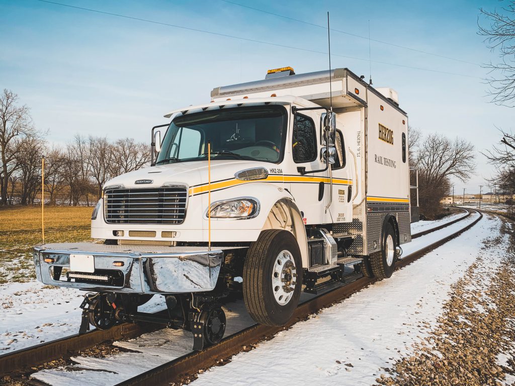
In an ideal world, railroaders would like to see UT testing get to where geometry testing is today, identifying precisely where exceptions are located. Relying on the human element, as is done in the current UT testing environment—especially in the type of stressful environment that gives you only 30 minutes of track time to work with—won’t cut it in the long run. Some sort of Artificial Intelligence will be needed to get to the point of truly automated defect detection. Technology providers are also thinking along the same lines.
Herzog Services, Inc., for example, has begun incorporating vision systems that integrate photos of the rail into the operator’s view, with future development aimed at automatically measuring the depth of crushed heads. HSI is also developing neural network-type of review capability within its continuous-test software to help analysts review rail conditions faster than it can with the current process.
Sperry Rail has begun incorporating additional technologies, such as joint bar inspection, eddy current, and vision systems to its non-stop testing equipment. The application of eddy current, a non-destructive inspection method that uses electromechanical induction to detect and characterize defects that occur on or below the surface of the rail, will enable Sperry to detect the types of damage associated with RCF. Sperry’s eddy current technology was implemented on a Class 1 railway last year.
Last but not least, Sperry Rail has introduced Elmer®, an artificial intelligence tool named after the company’s founder, that uses machine learning based on neural networks to process data from detection systems to identify patterns that may indicate the presence of defects. The system learns from the data gathered by ultrasound, induction, and eddy current inspection methods, and applies modern, AI-driven data analysis.
These research efforts and new technologies represent the next development wave in this crucial area of track testing.
Editor’s Note: A longer version of this article and several related pieces appear in the January print issue of Railway Track & Structures magazine.
Media
RELATED ARTICLES