EMFI Technology Development for Rolling Contact Fatigue Characterization in Rails
Written by Anish Poudel, PhD, Principal Investigator II NDT, MxV RailCourtesy of MxV Rail
ATLANTA - Railway Track & Structures, April Issue: Optimal management of rolling contact fatigue (RCF) in rails requires reliable, effective, and efficient non-destructive evaluation (NDE) technologies for detecting and characterizing surface damages.
MxV Rail worked in conjunction with Canada-based Athena Industrial Services, Ltd. (Athena) to introduce in-motion electromagnetic field imaging (EMFI) technology as a means of detecting and characterizing rolling contact fatigue (RCF) in rails. A technology originally developed for mapping corrosion and determining stress corrosion cracking in pipelines for the oil and gas industry, EMFI has been repurposed for RCF detection and characterization under the Association of American Railroads’ (AAR) Strategic Research Initiatives (SRI) program.
As a non-contact NDE method, EMFI uses an exciter core and coil to generate a focused electromagnetic field (EMF) in the rail head. A total energy sensor is used to measure the exact strength of the field emitted by the exciter coil assembly. The sensor also uses a series of antennas (receivers) precisely placed around the periphery of the excitation field to create a full three-dimensional (3D) map of the EMF shape changes. The changes in the local magnetic field strength of the back EMF generated by the surface eddy currents are measured by these antennas. In turn, the antenna coils produce a sine wave-like signal that is proportional to the position of the average magnetic field passing through each sensor element. The change in signal level is proportional to the depth of the encountered cracks, i.e., the deeper the crack, the larger the shift or deviation from the undisturbed field, thereby allowing the depth of the crack to be quantified. Outside literature describes the details of the technology.
This project allowed MxV Rail to help facilitate the development and evaluate the technology readiness level (TRL) of Athena’s EMFI technology for future commercial deployment or implementation in revenue-service. The AAR/SRI program provides the “bridge” that facilitates the development of innovative technologies for railway applications with the potential goal of revenue service implementation. Figure 1 illustrates the various phases/TRL of the EMFI development project. Several tests were designed between project phases at Athena and MxV Rail to bring this technology to the railroads. Phase I corresponds to TRL 3 (proof of concept), and Phase V corresponds to TRL 7 (field testing). During the life cycle of this project, several iterations of hardware and software were made. Each iteration further refined the technology for determining the RCF crack depths to further the grinding initiatives of a field deployable EMFI system.
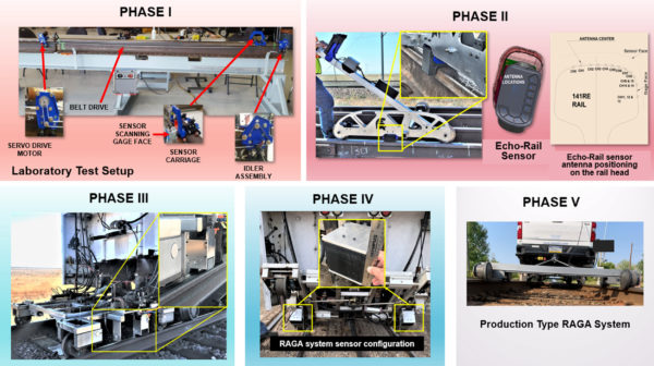
There were significant design modifications between the earlier generation sensor array (Phases I-III) and the fourth-generation sensor array (Phase IV). The development of the fourth-generation sensor, named “RAGA” by the manufacturer, focused on meeting the in-service inspection requirements (e.g., the ability to inspect through switches, frogs, crossings, joint bars, guard rails, and vertically offset rails). The EMFI sensor (both prior and current) operates in the “shadow” of a railcar or trolley wheel. By selecting this location for the EMFI sensor, researchers/developers were able to use the wheel as a guard for the sensor so that the sensor can travel a path identical to that of the railcar wheel.
Field testing was performed on a test track segment with replaceable rail retrieved from a heavily used curve. The rail installed as the outside rail was 52 feet long, and the rail installed as the inside rail was 66 feet long. There were nine measurement locations on the outside rail and 10 measurement locations on the inside rail, each specified by tie number. These test rails were also characterized by taking both MiniProf rail profile and liquid dye penetrant (PT) measurements at each specified location. The EMFI test runs, made at crawling speeds and at 5, 10, and 15 mph, were repeated five times at each speed. A target grind depth was determined based on the aggregate data, and the rails were ground accordingly. Instead of removing the RCF cracks entirely, the grinding was intended to leave the cracks behind to allow the destructive analysis to compare and validate the post-grind EMFI measurements. After grinding, the EMFI, Miniprof, and PT measurements were repeated. The rails were removed for destructive testing, which involved sectioning the rails and examining the cracks at each measurement location.
Field Testing and Results
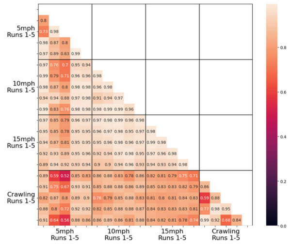
A correlation study was first conducted to test the repeatability of the EMFI system. Overall, many of the correlation results between different speeds and runs showed a Pearson’s correlation coefficient (PCC) of 0.80 or above (Figure 2). The low correlations that occurred between the crawling and 5-mph run on the low rail were expected due to issues in exact signal alignment (starting and stopping distances) and differences in the encoding steps used for different speeds.
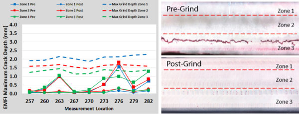
The EMFI RAGA sensor has several antennas positioned to measure and map EMF responses along the rail head (from gage corner to the field corner). This positioning of the antennas allows the mapping of RCF crack depth in different locations within the rail head. Three zones (Zone 1-Gage, Zone 2-Center, and Zone 3-Field) were selected to represent different sections of the rail head, and the maximum value from each channel located in the three zones was selected for RCF crack depth analysis. Similarly, the maximum grind depth was determined by calculating the vertical distance differences (W1) value between pre- and post-grind MiniProf measurements. Figure 3 shows the pre- and post-grind EMFI maximum RCF crack depths for three zones in the low rail along with the maximum grind depths and PT measurements for low rail tie location 273.
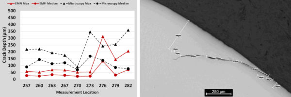
After the post-grind measurements were taken, the test rails were removed and dissected at all measurement locations for destructive microscopy analysis. This analysis was performed to determine the remaining crack depth values. The maximum crack depth value measured was 427 µm with an average crack depth value of 117 µm and a standard deviation of 90 µm. Figure 4(a) shows a comparison of the EMFI and microscopy findings for Zone 3 of the post-grind low rail. The EMFI system provides reasonable quantitative measurements, but crack depths in the range of 0 to 0.5 mm are insignificant at the lift-off where the sensor is currently being operated. These crack depths can be affected by grinding marks and are within the error band of the EMFI sensor. Based on the different measurement methods employed, it is extremely difficult to correlate EMFI readings with the precise crack depths because the EMFI system reports cracks within a volume of rail, and the microscopy is focused on a particular cross section. Figure 4(b) shows an example of the deepest remaining crack at tie location 273 after grinding, which is approximately 0.3 mm.
Conclusions and Path Forward
The revised electronics and the EMFI RAGA sensor allowed for increased data sampling frequency as well as improved signal-to-noise-ratio performance. The new sensor achieved sustained data acquisition rates of at least 2,000 samples per second. The key findings of the Phase IV research are as follows:
Run-to-run testing demonstrated a high correlation among five runs for the same and different speeds up to 15 mph, with runs within the same speed having the highest correlation.
Pre- and post-grind crack depth trends were generally captured by the EMFI system, but an exact accuracy value is difficult to state due to the fundamental differences in measurement techniques.
EMFI crack depth values between 0 and 0.5 mm are considered insignificant at the lift-off where the sensor is currently being operated. These crack depths can be affected by grinding marks and are within the error band of the EMFI sensor.
MxV Rail recently completed work with a revenue service trial of the production-type EMFI system that will be reported in future publications. Athena is working with its commercial partners to bring this technology forward for deployment in the North American railroads.
References
1. Poudel, A., K. Morrison, and B. Lindeman. 2023. “Evaluating Electromagnetic Field Imaging for Use in RCF Crack Depth Analysis.” Technology Digest TD23-004. AAR/MxV Rail. Pueblo, CO.
2. Poudel, A. and M. Witte. 2021. “Validation of In-Motion ECHO-Rail System for RCD Crack Depth Measurement.” Technology Digest TD21-012. AAR/Transportation Technology Center, Inc. (TTCI)/MxV Rail. Pueblo, CO..
3. Poudel, A. and M. Witte, M. 2020. “Evaluation of In-Motion ECHO-Rail RCD Measurement System.” Technology Digest TD20-007, AAR/TTCI. Pueblo, CO.
4. Poudel, A. and M. Witte. 2020. 2020. “Evaluation of In-Motion ECHO-Rail RCD Measurement System.” Technology Digest TD20-006, AAR/TTCI. Pueblo, CO.
5. Poudel, A., M. Witte, and P. Gies. 2019. Rolling Contact Damage Characterization on Railroad Rails Using Electromagnetic Field Imaging (EMFI). Materials Evaluation 77 (7): 951-965. American Society for Nondestructive Testing. Columbus, OH.
6. Witte, M. and A. Poudel. 2018. “Measuring Rolling Contact Damage in Rails Using EMFI.” Technology Digest TD18-016. AAR/TTCI.
Pueblo, CO.
Media
RELATED ARTICLES