High-Speed Adjustable Perturbation Test Track for Vehicle Testing at the Transportation Technology Center
Written by TTC Operated by ENSCO
Courtesy of ENSCO
RAILWAY TRACK AND STRUCTURES, NOVEMBER 2023 ISSUE, TTC Operated by ENSCO
Authors: Radim Bruzek, R&D Program Manager, ENSCO, Inc., Springfield, Va., Sean Woods, R&D Project Manager, ENSCO, Inc., Pueblo, Colo., Jennifer Zahacewski, Project Manager, ENSCO, Inc., Chambersburg, Pa., Alexandra D’Andrea, Program Manager, Track Research Division, Federal Railroad Administration Office of Research, Development, and Technology, Washington, DC.
Several years ago, the Federal Railroad Administration (FRA) installed a specially designed adjustable track at the Transportation Technology Center (TTC) in Pueblo, CO. This track, referred to as the High-Speed Adjustable Perturbation Test Track (HS-APTT), can be configured to introduce known geometry perturbations. The HS-APTT, shown in Figure 1, consists of a 500-foot-long tangent slab track within the Railroad Test Track Loop (RTT) with specially designed steel cross ties, tie plates, and fasteners which allow adjustments to the profile, alignment, crosslevel, and gauge.
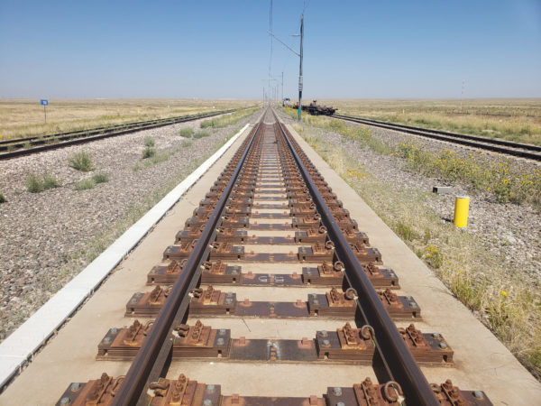
Figure 1: HS-APTT at the RTT Loop at the TTC
Vertical deviations, up to a maximum of ±2 inches can be created by installing shim plates between the tie and tie plate in increments of 1/16-inch. Lateral deviations, up to a maximum of ±1.5 inches, are made by moving the tie plate to the gage or field sides in increments of 1/4-inch. The adjustment mechanism is illustrated in Figure 2.
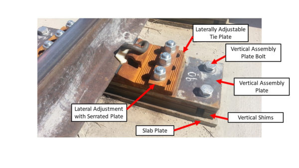
Figure 2: HS-APTT Vertical and Lateral Adjustment Mechanism
Profile, alignment, gage, and crosslevel perturbations with desired amplitudes and wavelengths are introduced into the track by making required adjustments at multiple ties. In addition, track properties such as resiliency and damping can be adjusted and controlled. The ability to precisely introduce geometry perturbations into the track allows researchers to study vehicle response to known track inputs and to evaluate the accuracy of various Track Geometry Measurement Systems (TGMS).
To use the adjustable slab track as a controlled test bed, the introduced track geometry must be precisely known. The process of introducing perturbations into the track does provide a high degree of control over the geometry. However, inconsistencies in the slab and small variations in the fasteners result in slight deviations between the true installed geometry and the installation plan. Therefore, geometry must be measured directly, as opposed to being inferred from the configuration of the track fasteners and tie plates. The process of precisely determining the actual track geometry is known as ground truth measurement. This ground truth is then used as the standard for assessing the accuracy of a track geometry system or for any other uses of the adjustable slab track.
Initially the ground truth track geometry was determined using total station-based surveying approaches. However, this process was time consuming and susceptible to loss of accuracy due to wind and heat mirage. Additionally, this approach was not accurate enough to evaluate typical vehicle mounted track measurement systems. A fast and accurate method of measuring the ground truth track geometry was needed.
FRA contracted ENSCO to evaluate existing solutions for ground truth measurement of the HS-APTT. The evaluation criteria were ease of setup and use, high accuracy, and the ability to independently verify the geometry parameters. ENSCO’s investigation of existing survey technologies found no viable solution, mainly due to insufficient accuracy over the length of the 500‐foot section of track, and concerns about traceability of the measurements. Intellectual property concerns with the manufacturers would have prevented independent validation of the raw measurements and the processed outputs. As a result, FRA asked ENSCO to develop a suitable custom solution, the Ground Truth Measurement System (GTMS).
The GTMS consists of a three-wheeled measurement cart designed to minimize weight and ensure the frame provides a stable platform under any combination of profile perturbations installed on the test track. The cart contains four high-accuracy laser profile scanners, two for locating the left and right rail heads, and two for locating reference monuments permanently installed on the steel ties of the HS-APTT. The beam is attached to the cart frame via rubber isolators to reduce the effect of any unintended shock the cart may experience. The user interface is a custom software module which provides a live view of the rail head and monument targets on the ties to give the operator continuous feedback on the clarity of the scanners’ targets. The operator can review the image to confirm its good quality and that the rails and the monuments are clear of ballast, vegetation, or other debris that may obstruct the view prior to recording the data. The GTMS cart in operation is shown in Figure 3.
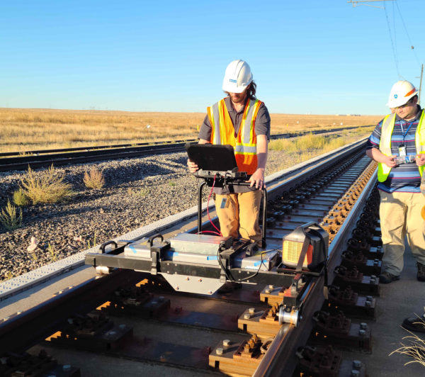
Figure 3. Ground Truth Measurement System in Operation on the HS-APTT
In addition to operations on the existing tangent adjustable slab track, the cart was designed to operate on a planned adjustable curve track in the future. The adjustable curve track will be a 1.25-degree curve on the RTT near the tangent track and use a similar track-bed design with steel ties embedded in a concrete slab. The design of the measurement cart uses two double-flanged wheels on one side to keep the cart tracking along the left rail. To accommodate 1.25-degree curvature while still tracking along the left rail, a small clearance between the wheel flanges and the rail was added to prevent wheel binding in curve.
The GTMS achieves very high accuracy because it only uses laser profile scanners to determine the relative position of the rail heads from the reference monuments. The GTMS does not include any inertial system and the results are not affected by any potential errors in inertial calculations and corrections. However, to achieve the highest levels of accuracy, the position of reference monuments must be precisely known, and the ground truth cart must be accurately calibrated prior to use.
The reference monuments consist of a pair of 1.5-inch steel cubes welded to each steel tie. This installation is less likely to be disturbed by track work, rail traffic, and other testing activities. The exact position of the monuments is determined through high precision surveying as shown in Figure 4. The monuments’ measurements are collected once a year to account for track settling or other changes in position. The monument survey is also conducted any time there is a reason to believe the position of the monuments has changed. The monument coordinates are used each time the measurement cart collects ground truth data.
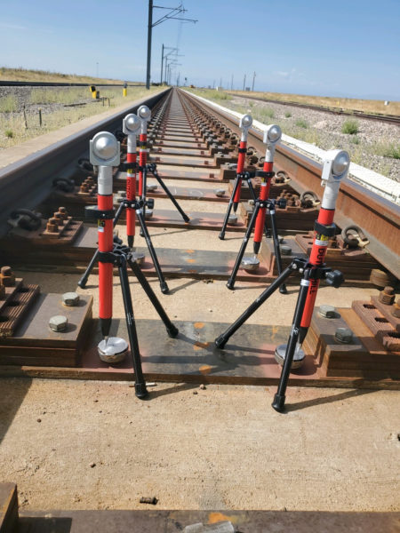
Figure 4: High Precision Survey of Reference Monuments (Cylinders fit over the survey cubes)
ENSCO designed a special calibration bar to calibrate the measurement cart. The bar is made of two rectangular carbon fiber tubes with right-angle targets located at each end, near where the rail heads would be when the bar is placed on the track. Because the field of view of the rail and monument scanners do not overlap, two additional targets were added to the calibration bar to accurately align the monument scanners. The calibration bar is shown in Figure 5. Prior to use, this bar is precisely measured in a metrology laboratory using a Coordinate Measuring Machine (CMM) so that the known dimensions can be used by the GTMS to align the scanners and correct any internal offsets. Carbon fiber tubing was selected for the design because of its extremely low coefficient of thermal expansion. This approach minimizes error introduced due to thermal expansion between when the calibration bar is measured with a CMM and when it is used to calibrate the GTMS in the field. GTMS calibration is performed before each ground truth survey.
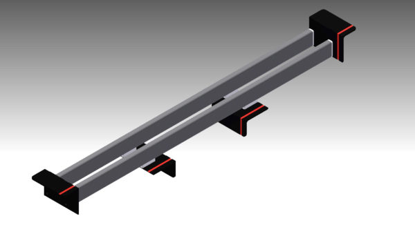
Figure 5. Carbon Fiber Calibration Bar
FRA has utilized the HS-APTT to assess and advance the accuracy of the TGMS systems deployed in its inspection fleet, including the DOTX 216. In the spring of 2024 ENSCO will conduct extensive testing on the HS-APTT involving a fully instrumented tank car with instrumented wheelsets (IWS). This testing, which is part of ongoing FRA tank car research, will analyze vehicle response and wheel forces under specific combinations of track geometry perturbations and train handling scenarios. This effort will enhance understanding of tank car and rail system behavior and resilience in potentially dangerous operating conditions.
The HS-APTT at TTC, along with its planned addition of an adjustable curve track, represents a unique capability for TGMS development, assessment, and calibration as well as precisely controlled vehicle track interaction research.
The authors would like to acknowledge Ali Tajaddini, formerly of FRA’s Track Research Division, for his role in identifying the need for this test bed and guiding its construction and validation.