Quantifying Rail Life Extension with Infinite Rail Grinding Pattern Control
Written by Jeff Tuzik, Managing Editor, Interface Journal
RAILWAY TRACK & STRUCTURES, OCTOBER 2023 ISSUE:Preventive rail grinding is a well-established practice for extending rail life. And by optimizing wheel/rail interaction and controlling the development and growth of surface damage like rolling contact fatigue, rail grinding has proven itself to be one of the industry’s best tools for managing one of its most valuable assets.
Ed. Note: Some of the images in this story are a little soft. If you have trouble reading the data on the images, please see the digital edition of the October 2023 issue, linked below.
Hardware and software developments have enabled companies like Loram Maintenance of Way, Inc., to yield increasingly more precise rail profiles, less unnecessary metal removal, and a more customized approach to the entire rail grinding process. In recent years, Loram has also undertaken to quantify the effects of these new techniques and technologies on metrics like profile-deviation and rail-life extension.
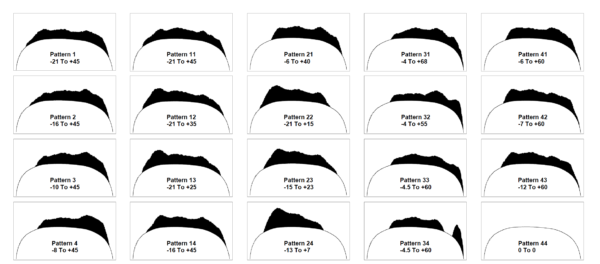
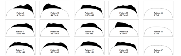
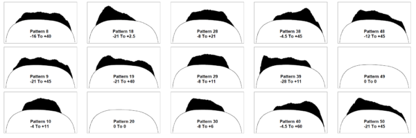
Figure 1: An example of a pre-set grind pattern array.
In practice, rail profiles are implemented by grinders running specific grind-patterns to achieve a desired template or rail profile shape. These patterns are essentially lists of angles at which the individual grind modules contact the rail to achieve a specific profile. The amount of power provided to the modules is another variable that can be adjusted based on the desired metal-removal rate. Traditionally, rail grinders had a set number of up to 50 static patterns that that were effectively hard-coded into the grinder firmware/software. An operator could then choose the pattern, module amps, and grinder speed at 1 mile-per-hour increments for a given pass. “These static patterns can achieve good results with a skilled operator, but due to the limitations, there is no single ‘perfect’ cut,” Chris Lidberg, a Product Manager at Loram told attendees at the 2023 Wheel/Rail Interaction Conference.
It’s also important to note that a grind pattern will not produce the same result on different rails with different profile shapes. “Static patterns are based on a new-profile shape, but you’re going to encounter a lot of different shapes in the field,” he said.
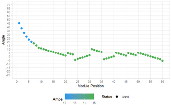
Figure 2. Chart shows grind module angles and power application.
Figure 2 shows an example grind pattern for a 120-stone rail grinder. On the Y axis, negative angles indicate locations to the field-side of the rail center-line, while positive angles are to the gauge-side. Each dot on the graph represents one module, and the color of the dot represents the power, in amps, supplied to the module.
Over the years, a number of techniques have been developed to ensure that the as-ground rail profile matches the design-profile, and that as little as necessary metal is removed to control the growth of rolling contact fatigue (RCF) and achieve the target profile. One of the ways this is done is by taking rail profile measurements pre- and post-grind (or after a single grind pass) to determine deviation from the target profile, and the amount of metal required to be removed. One of the more recent developments in rail grinding software has been the ability to perform these types of measurements and analyses in real-time, Lidberg said. “Based on [data from] a single pass, we can determine exactly how many more passes it will take to hit the metal-removal target.”
Figure 3. Chris Lidberg, Product Manager at Loram Maintenance of Way. Photo: Mike Yuhas
In 2019, Loram began to implement its dynamic pattern creation system. The system compares the target profile to a pre-grind profile measurement and automatically adjusts the modules to grind to the target — hence, the pattern is created rather than selected from a list of static patterns. Instead of 50 static patterns applied at 1-mph increments, the dynamic pattern system can apply a near infinite number of patterns at 0.1-mph increments. “We’re able to achieve a much finer degree of control this way,” Lidberg said. It also makes it easier for the operator to avoid unnecessary metal removal due to a potential mismatch of the rail and grind pattern, he added.
While the value of rail grinding this way is fairly intuitive and easy to demonstrate, it can be difficult to quantify, and thus justify as a maintenance expenditure. In order to measure and quantify the differences between the standard pattern-selection versus the new pattern-creation method, Loram selected a subdivision with a robust history of rail grinding and profile measurement. Beginning in 2019, they began to grind this subdivision under the new pattern-creation system, and then compared the results. “We could see from the data that we removed less metal, and deviated less from the target profiles when we implemented pattern-creation,” Lidberg said. To quantify the results, Loram looked specifically at low rail vertical-, and high rail gauge-wear rates.
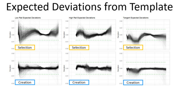
Figure 4. The pattern-creation process results in less deviation between the design-profile, and the as-ground profile.
The findings from this study, which were presented at WRI in 2021, indicate that due to the reduction in vertical wear rates, the low rail is predicted to have a 19% increase in expected rail life, while the high rail showed a 13.5% increase in predicted rail life. Since then, Loram has continued to refine its ability to accurately model natural wear rates and better quantify the effects of pattern-creation grinding at a more granular level, Lidberg noted.
Loram’s first step in refining their comparative grinding analyses was to develop a model for each test site based on historical data. The new natural wear rate model considers traffic patterns, wheel and rail profiles, friction conditions, and wheel and rail metallurgy. Using this more robust wear model, rail life can be modeled, out to the point of end-of-life, using data from pattern-selection and pattern-creation grinding data. “This allowed us to model the evolution of rail wear and damage with a great deal of confidence,” Lidberg said.
According to the simulations, sharp curves (sites with a high natural wear rate) saw the greatest benefit under a pattern-creation grinding regime. In one such case, the low rail saw a 38.7% reduction in vertical wear over a period of 80 MGT. This was achieved by keeping the contact patch in a more optimal location by better implementing the target profile, Lidberg said. The study also found that combined wear rates on the high rail were more predictable and had less variability from site to site under a pattern-creation regime.
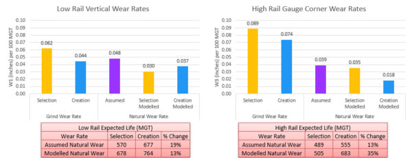
Figure 6. Rail wear projections with updated natural wear rates.
Data from these simulations has also enabled Loram to predict natural wear rates more accurately as a baseline for comparative analyses. While its initial 2021 analysis used an assumed natural wear rate of 0.048 inches vertical wear per 100 MGT for the low rail and 0.039 inches gauge corner wear per 100 MGT for the high rail, the model provided more accurate numbers for both pattern-selection-ground rail and patter-creation-ground rail. The figures for low rail vertical wear are: 0.030 inches/100 MGT for selection-grinding; 0.037 inches/100 MGT for creation-grinding. And the figures for high rail gauge corner wear are: 0.035 inches/100 MGT for selection-grinding; 0.018 inches/100 MGT for creation-grinding.
Using these updated figures, Loram predicts an overall life extension of 13% on the low rail life, and 35% on the high rail. “This shows that it’s important to verify your assumed wear rates,” Lidberg said.
Taken altogether, the results of Loram’s simulations and analyses seem to bear out the efficacy of tailoring grind patterns to specific sites, rather than using pre-set patterns to target a “best-fit” approach. And while skilled operators can, and have, achieved great results via this traditional method of grinding, this new approach of in-situ pattern-creation grinding removes a lot of the guesswork and potential for error.
Jeff Tuzik is Managing Editor of Interface Journal ( www.interfacejournal.com ).
This article is based on a presentation made at the WRI 2023 Conference.