A Deeper Look: Preventing Brittle Fracture in Steel
Written by Gary T. Fry, Contributor
Gary Fry
ATLANTA –– Sudden brittle fracture of a loaded steel component occurs when a crack in the steel grows unstoppably at a speed of 3.7 miles per second—roughly the speed of sound in steel.
Sudden brittle fracture of a loaded steel component occurs when a crack in the steel grows unstoppably at a speed of 3.7 miles per second—roughly the speed of sound in steel. When a brittle fracture occurs, the structural integrity of the component and the structural system it supports is usually compromised. The consequences of such a fracture depend specifically on what was being supported at the time of the failure.
The load that triggers a brittle fracture is usually smaller than loads that the component had successfully carried many times before—maybe millions of times before. All told, brittle fracture gives an impression of being unpredictable and uncontrollable. Fortunately, it is neither. Let’s take a deeper look at preventing brittle fracture in steel.
Brittle fracture failures were observed from the earliest days of using steel to make structural components starting in the late 1850s. Various explanations for the phenomenon were offered, along with recommendations for avoiding such failures. Despite considerable research efforts, the most popular explanations fell short, and the failures persisted.
An effective explanation finally emerged in 1920 when Alan Arnold Griffith, an English mechanical engineer, published an analysis that described brittle fracture in terms of an unfavorable energy imbalance (Griffith 1920). His analysis was notable in several ways, but the most significant feature is including a term for the energy required to form crack-surfaces when calculating the total potential energy of the loaded component. The analysis established that when the formation of new crack-surfaces results in a lower energy state for a loaded, and cracked, component, then the crack will extend.
Griffith’s paper is broadly recognized as the origin of the modern field of fracture mechanics. Over the ensuing century, fracture mechanics has been a consistently impactful and active research enterprise around the globe. These efforts have produced many practical outcomes that are directly applicable to railway engineering.
To begin, it is important to recognize that fracture of steel and fatigue of steel go hand in hand (Fry 2022a; Fry 2022b; Fry 2022c; Fry 2024). Modern design methods for steel address the issues of fracture and fatigue directly. To do this, there are generally four key considerations: 1) desired life expectancy of the system; 2) system inspection and maintenance programs; 3) loading environment; and 4) material properties—especially strength, ductility, and fracture toughness.
To highlight the key features, we will consider the simple example of a steel plate in tension. Figure 1 shows axial stress capacities for an uncracked steel plate. The alloy is an open-hearth steel with 65 ksi tensile strength, 33 ksi yield strength, and 18 ksi design strength.
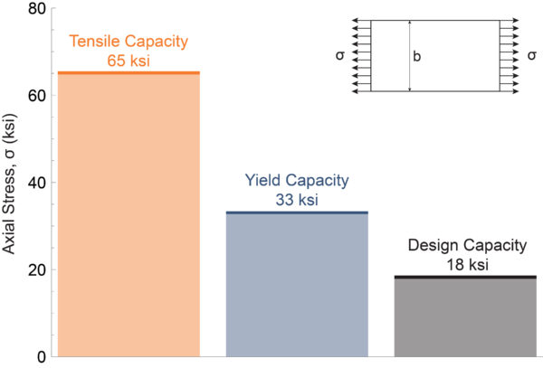
Figure 1. Plot of axial stress capacity of an uncracked steel plate. The alloy is an early 20th century open-hearth steel with 65 ksi tensile strength, 33 ksi yield strength, and 18 ksi design strength. (Courtesy: Gary T. Fry)
The steel used in this example is the type widely used in railway bridges in the early 20th century. Design norms at the time relied heavily on the strength and ductility of the steel. Ductility is a measure of steel’s ability to deform plastically and is often considered an indicator of steel quality. Steel with excessive metallurgical discontinuities usually has poor ductility. Steel strength is as it seems. It is a measure of the steel’s ability to resist load and is usually expressed in units of pressure: for example, kilo-pounds per square inch (ksi). The design capacity for steel is usually a value well below the yield strength of the steel: for example, 55% of the yield strength.
Imagine that we have built a steel railway bridge. All of the members are designed so that the demand on the steel is below the design capacity. After many years of service and the passage of thousands of trains a member in the bridge fractured while a train was crossing. The train was not unusual in its makeup or car weights. Similar trains had crossed the bridge every day for decades. It is later determined that the fractured member had developed a small fatigue crack which caused the fracture of the member. The crack was too small to reliably find during a routine inspection of the bridge.
Brittle fractures originating at cracks occurred not only in railway bridges but also in ships, large storage tanks for liquids—notably a molasses tank failure in Boston in 1919, pressure vessels, machinery, and other components subjected to repeated loading. Adding to the puzzle, sometimes large, easily found cracks would form without causing a brittle fracture—obviously a much-preferred outcome. Until Griffith published his work, it was anyone’s guess as to why some steel could tolerate large cracks and seemingly identical steel fractured in the presence of very small cracks. The answer was that steel had another material property that had not been recognized: fracture toughness. Fracture toughness is a measure of steel’s sensitivity to the presence of a crack. It is related the energy required to form new crack-surfaces in the steel.
Fracture toughness is a much more complicated material property to measure compared to strength or ductility. Since fracture toughness has no meaning in the absence of a crack, the test specimens must contain a very sharp notch. Oftentimes, in addition to the sharp notch, the specimens are subjected to a loading that creates an even sharper fatigue crack at the root of the notch prior to testing. This is a preferred procedure for any toughness test and is a requirement in many standard testing protocols. Like fatigue strength (Fry 2024), fracture toughness values can be highly variable, even from identical specimens machined from the same piece of steel and tested under identical conditions.
There are other complicating issues. Notably, the fracture toughness value for steel is very temperature dependent, even within temperature ranges associated with normal seasonal weather patterns. Generally, fracture toughness of steel is lower at cold temperatures and higher at hot temperatures. Hence, several tests are performed at various temperatures to fully characterize the property for a sample of an alloy. Fry (2022b) provides an explanation of temperature effects on fracture toughness values, critical crack size, and the more frequent occurrence of rail and wheel fractures on cold winter days as compared to hot summer days.
It suffices to say that the mathematics, the materials science, and the engineering associated with fracture mechanics is nuanced and complex…and fascinating! There are many reference texts dedicated to the subject. The comprehensive treatment in Barsom and Rolfe (1999) is a great place to start.
Despite the inherent complexity of the topic, there are a few essential features that can be illustrated in a straight-forward way. The first feature is the basic effect of a crack on the capacity of a steel member. Figure 2 is a plot of results from a capacity analysis of a steel plate that contains a crack of length, a, growing into one of its edges (see inset drawing). In this analysis, the plate width, b, was given a value of 10 in. We will use the same alloy as before and additionally include a fracture toughness value of 50 ksi √in.
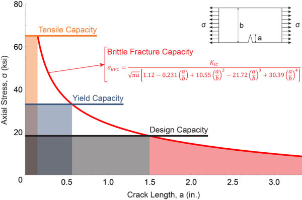
Figure 2. Plot of axial stress capacity of a cracked steel plate. The plate is 10 in. wide. The alloy is an open-hearth steel with 65 ksi tensile strength, 33 ksi yield strength, 18 ksi design strength, and plane-strain fracture toughness, KIC, of 50 ksi √in. (Courtesy: Gary T. Fry)
As in Figure 1, the vertical axis in Figure 2 represents axial stress in ksi. The plot in Figure 2 also contains a horizontal axis representing crack length. For reference, Figure 2 includes horizontal lines that denote the tensile capacity (orange), yield capacity (blue), and design capacity (black). The red curve in Figure 2 shows the brittle fracture capacity, σBFC, which is a function of the crack length, a, the plate width, b, and the plane-strain fracture toughness value for the steel, KIC. The equation for brittle fracture capacity is included in the figure. Note that this equation is
based on a solution by Gross et al. (1964) applicable only to a plate cracked and loaded as indicated in the inset drawing in Figure 2. Solutions for many other component geometries, crack configurations, and loading conditions have been derived and compiled (e.g., Tada et al. 2000).
The most important feature to note in Figure 2, is the intersection between the black line denoting design capacity and the red line denoting brittle fracture capacity. The intersection occurs at a crack length of 1.5 in. For cracks longer than 1.5 in., the brittle fracture capacity is lower than the design capacity. Therefore, when loaded to 18 ksi, and cracked as indicated, the critical crack size for this steel plate is 1.5 in. Stated another way, if a fatigue crack is allowed to grow to 1.5 in., and the loading remains at 18 ksi, a plate made from this particular steel is at severe risk of brittle fracture.
This is great information to have. For example, it allows us to define the requirements for an inspection and maintenance program. In this case, to safely operate at the design capacity, our inspection and maintenance procedures need to reliably detect and repair cracks well before they reach a length of 1.5 in. The information also gives insight for potentially reducing operating loads in the presence of cracks, until repairs are completed.
Another takeaway that can be easily described is the basic effect of fracture toughness on the capacity of a cracked steel member. Consider the three brittle fracture capacity plots in Figure 3: two dashed red lines and one solid red line. These lines represent three different values of plane-strain fracture toughness, KIC: 25 ksi √in.; 50 ksi √ in.; and 75 ksi √in. Large red dots in Figure 3 indicate where the three red lines intersect the design capacity: at crack lengths of 0.5 in., 1.5 in., and 2.5 in. respectively. And with that, we clearly see the benefit that larger fracture toughness values provide—larger values of crack length before brittle fracture occurs at a given load level.
An appropriate value of fracture toughness to specify in a design is one that reliably ensures, under a given loading, that cracks can reach a detectable size before a fracture occurs. Of course, this statement assumes the existence of a defined inspection program that is keyed to reliably detect cracks.
In isolation, fracture toughness alone cannot prevent cracks from developing in steel and it cannot prevent fractures from occurring in steel. Fracture toughness has minimal effect on fatigue crack initiation and minimal effect on fatigue crack growth rates. Dialing up fracture toughness simply buys us larger crack sizes before fracture occurs, which can make detecting the cracks easier—but only if we’re looking for them.
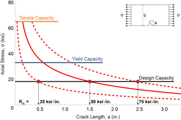
Figure 3. Plot of axial stress capacity of a cracked steel plate. The plate is 10 in. wide. The alloy is an open-hearth steel with 65 ksi tensile strength, 33 ksi yield strength, 18 ksi design strength, and three values for plane-strain fracture toughness, KIC:25 ksi √in.; 50 ksi √in.; and 75 ksi √in. (Courtesy: Gary T. Fry)
In summary, preventing brittle fractures in steel requires a directed approach that considers three factors simultaneously: applied loading; material properties—including strength and fracture toughness; and inspection and maintenance programs. Neglecting any one of these three factors significantly and substantially reduces the reliability of steel components.
Notably, in terms of railway engineering, it is not common practice to inspect railway wheels for internal fatigue defects that can cause wheel failures. As a result, preventable accidents occur every year. All that is needed to move forward is industry-wide coordination and off-the-shelf ultrasonic inspection equipment.
References
Barsom, John M. and Stanley T. Rolfe. 1999. Fracture and Fatigue Control in Structures: Applications of Fracture Mechanics. West Conshohocken, Pennsylvania: ASTM.
Fry, Gary T. 2022a. “Metal Fatigue: How Dangerous Fatigue Cracks Develop in Sound Steel.” Railway Age. January: pp. 36-38. New York: Simmons-Boardman.
Fry, Gary T. 2022b. “Metal Fracture: The Fatigue Cycle that Really Counts.” Railway Age. February: pp. 41-43. New York: Simmons-Boardman.
Fry, Gary T. 2022c. “Ultrasonic Testing of Steel: Seeing Invisible Defects using Inaudible Sounds.” Railway Age. March: pp. 44-46. New York: Simmons-Boardman.
Fry, Gary T. 2024. “Tackling Fatigue Defects in Steel.” Railway Track and Structures. February: pp. 9-12. Omaha, Nebraska: Simmons-Boardman.
Griffith, A. A. 1920. “The Phenomena of Rupture and Flow in Solids.” Philosophical Transactions of the Royal Society of London. Series A. Containing Papers of a Mathematical or Physical Character. Vol. 221: pp. 163-198. London: Harrison and Sons, Ltd.
Gross, Bernard, John E. Srawley, and William F. Brown, Jr. 1964. “Stress Intensity Factors for a Single Notch Tension Specimen by Boundary Collocation of a Stress Function.” NASA TN D-2395. Washington, D. C.: National Aeronautics and Space Administration.
Tada, Hiroshi, Paul C. Paris, and George R. Irwin. 2000. The Stress Analysis of Cracks Handbook. Third Edition. New York: ASME Press.
Dr. Fry is the Vice President of Fry Technical Services, Inc. (https://www.frytechservices.com/). He has 30 years of experience in research and consulting on the fatigue and fracture behavior of structural metals and weldments. His research results have been incorporated into international codes of practice used in the design of structural components and systems including structural welds, railway and highway bridges, and high-rise commercial buildings in seismic risk zones. He has extensive experience performing in situ testing of railway bridges under live loading of trains, including high-speed passenger trains and heavy-axle-load freight trains. His research, publications, and consulting have advanced the state of the art in structural health monitoring and structural impairment detection.