Smart Rocks, Smart Tamper: Investigating the Mechanics of Ballast Tamping
Written by Jeff Tuzik, Managing Editor, Interface Journal
Courtesy of David Lester
ATLANTA - Railway Track & Structures, April 2024 Issue: There are many forces that work to deteriorate track geometry over time. These forces don’t begin and end at the wheel/rail interface; they are transmitted to the vehicles and their components and into the track structure and its components. On ballasted track, ballast absorbs these forces, and its maintenance is critical to preserving and correcting several types of track geometry defects.
Maintaining track geometry is an ongoing process that affects both safety and ride quality. “It’s akin to fixing potholes on a roadway before they become dangerous,” Fabian Hansmann, Deputy Director of Marketing at Plasser & Theurer/Plasser American told delegates at the 2023 Heavy Haul Wheel/Rail Interaction conference. “Small geometry deviations can grow exponentially worse if they’re not corrected early,” he added. Track geometry directly influences the condition and behavior of other components in the system such as the rail, fasteners, and ties. Through these components, forces are ultimately transmitted into the ballast, and as the ballast shifts, so too does the track.

“Tamping machines that combine ballast-packing and track alignment functions are a universally-adopted technology for maintaining ballasted track,” Hansmann said. They vary in design and specification but generally function on the same principle. “Consider a track geometry surface defect that has been identified and measured,” he added; the process of correcting the defect with a tamper consists of the following steps:
Centering: the tamping machinery is positioned at the defect site.
Insertion: the tamping tools are inserted into the ballast on both sides of a tie.
Squeeze/Oscillation: the tools lift the tie, perform a squeezing motion to fill the void beneath it, and oscillate to compact the ballast that fills the void.
The squeeze cycle typically occurs over 0.6 to 1.2 seconds. “This is where the magic happens,” Hansmann said. Depending on the characteristics and requirements of the rail system and the ballast conditions, there is nuance and variance in how the tamping parameters (like number of insertions and tamping cycle time) are applied. “Each part of this process is set by the operator, so the efficacy and quality of tamping is dependent on their experience,” he said. “Therein lies the potential for improving and optimizing the tamping process,” he added.
To better understand and to optimize the tamping process, Plasser & Theurer partnered with Penn State University to investigate tamper/ballast interaction at its most granular level, and take the first, early steps in developing a tamper that can assess and measure ballast characteristics, provide the operator with relevant data, and perform the work with precision and uniformity.

In order for a tamper to “know” ballast conditions and adjust its parameters, it requires a kind of tactile feedback. “It’s like a human hand gripping something. Your senses tell you the consistency of the material or the force you’re exerting,” said Yuliang Zhou, a graduate research assistant in civil engineering, specializing in structure health monitoring of railroad infrastructure, at Penn State University. To replicate this tactile sense, Zhou and Plasser & Theurer instrumented a tamper with a suite of measurement devices including accelerometers, strain gauges, pressure sensors, and angle encoders. Combined, these sensors allowed them to precisely monitor the input forces of each part of the tamping cycle. To measure the output — the ballast response — the team developed and deployed a number of “smart rocks” — wireless devices that are roughly the size of a ballast stone and contain an accelerometer, gyrometer, and a stress cell. “When placed at a tamping site, the sensors can directly measure the translation, acceleration, rotation, and stress [of the ballast] during tamping,” Zhou said.
With these tools, the research concept was to measure tamping input parameters (number of insertions, oscillation cycles, squeezing time and force), measure the ballast performance during tamping, and measure ballast performance after tamping. “This allows us to establish a direct link between input and performance,” he said.
Field testing was conducted at two sites representing two ballast conditions: one site with clean ballast, and one with fouled ballast. At each site, tests were conducted with varying squeeze time and number of insertions, while the lifting value (25mm) and squeeze pressure (35Hz) remained constant. Smart rock sensors in groups of six were placed beneath four ties, spaced 20 ties apart. These measured ballast reaction during and post-tamping.
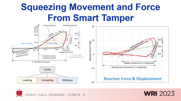
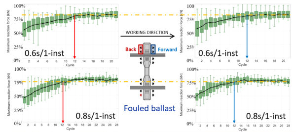
Figure 1 shows an ideal reaction force and displacement curve for a single squeezing cycle (on the left). The cycle is broken into three phases: loading, unloading, and withdrawal. This cycle is repeated multiple times during the tamping process. In practice, these values fluctuate slightly from cycle to cycle (as shown on the right). “The maximum values as measured across multiple cycles set the boundaries of reaction force and displacement for the sake of data analysis,” Zhou said. Figure 2 shows these maximum reaction forces in kilonewtons over the course of multiple squeezing cycles at the fouled ballast site for squeeze time values of 0.6 seconds and 0.8 seconds. “The maximum reaction force starts low and increases until it hits the maximum value and stabilizes at around the 12th cycle, or about 0.35 seconds,” Zhou said. This means that a longer squeeze time equates to more time spent at maximum force values.
From the perspective of the ballast, there are two primary ballast acceleration events: tamper tine insertion and the squeeze cycle. At the clean ballast site, these events followed a pattern of a smaller, shorter acceleration during insertion, and a longer, higher acceleration during the squeezing cycle. The fouled ballast site results were less clear, in some cases showing an opposite acceleration pattern with higher g-forces during insertion, and lower during the squeeze time. “Our guess is that fouled ballast has more fine particles and mud that absorb energy imparted by tine insertion and squeezing,” Zhou said.
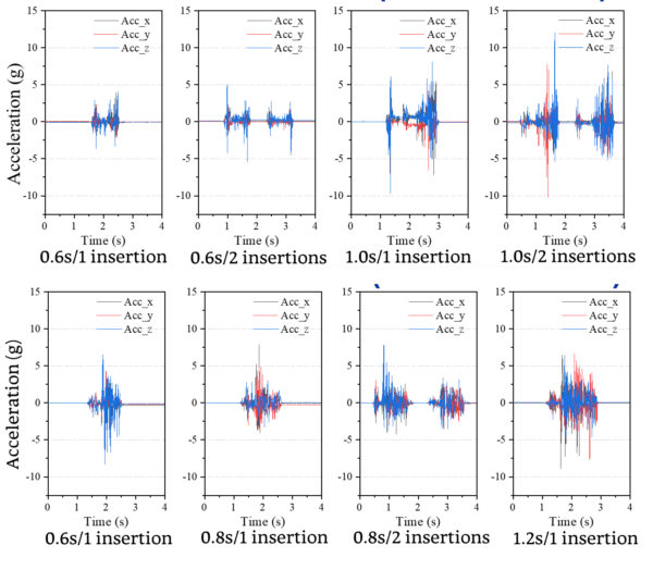
fouled ballast at multiple numbers of insertions and squeeze cycle lengths.
Figure 3 shows a comparison of ballast acceleration forces in clean ballast (above) and fouled (below) ballast at multiple numbers of insertions and squeeze cycle lengths. “Another way to frame this finding is that clean ballast appears to be more sensitive to tamping parameters in general,” he said.
The smart rocks also measured ballast rotation during tamping. Here the data showed that clean ballast exhibited a relatively high rate of rotational change compared to the fouled ballast, which averaged less than half the clean ballast values. When particle rotation is correlated to acceleration data, the overall picture is one in which clean ballast generally shows higher rotation for higher acceleration, while fouled ballast shows less rotation for all acceleration values.

Figure 4 shows a comparison of tamping force (input) and ballast bulk stress (output) for different cycle lengths. “The data shows that as tamping force increases, bulk stress increases quickly, and then tends to stabilize even as tool force stays constant,” Zhou said. This pattern is also apparent in the comparison of ballast bulk stress to tamping tool displacement – both increase rapidly, then (relatively) slowly level off over the course of a tamping cycle.
Although testing at these two sites is ongoing, there are some preliminary results on post-tamping ballast performance. To measure overall ballast stability, the team measured normalized ballast bulk stress over time. “If the smart rock stabilizes over time, it indicates the ballast has stabilized,” Zhou said.
Results at the clean ballast site show roughly similar stability for all test variables, except the combination of 1 insertion/0.6 seconds squeeze time. Results at the fouled ballast site are more divergent. Here, the ballast shows more consistent stability at 1 insertion/0.8 seconds, and 1 insertion/1.2 seconds squeeze time. “We believe that the fine particles and mud [in the fouled ballast] provide some dampening and stability that is disturbed by multiple insertions or more rapid cycles,” Zhou said. “However, this data represents a small sample over a fairly short period, and more testing and data analysis is required,” he added.
“For the time being, this investigation has yielded some general conclusions,” Zhou said. The first is that from the ballast’s perspective, the squeezing phase can broadly be divided into two phases – the initial disruption of the ballast structure as it is swept into the void left by the tie, and the compaction or interlocking of that ballast.
The second is that clean ballast is generally more responsive to tamping parameters and variables, and that longer cycles (1 second vs 0.6 seconds) tend to yield better results in terms of ballast stability. It also appears that the deficiencies of short squeeze times in clean ballast can be improved by multiple insertions. “From a tamping production standpoint, this means slowing the process down may result in slightly fewer feet per hour but will leave the ballast in a more stable condition that requires less frequent tamping,” Plasser & Theurer’s Hansmann said.
Penn State and Plasser & Theurer plan to conduct further field tests at these sites and perform additional data analyses on the tamping and post-tamping results. “Ultimately,” Hansmann said, “the goal is to reach a level of confidence in these measurements that tampers can be outfitted with feedback mechanisms that indicate to the operator the quality of the ballast, the ideal squeeze cycle, and whether an additional insertion is required.” Looking further to the future, tampers may be able to adjust their parameters and operate autonomously, leaving behind ballast that is stable and consistent, and track that is free of geometry defects.
Jeff Tuzik is Managing Editor of Interface Journal ( www.interfacejournal.com )
This article is based on a presentation made at the 2023 Heavy Haul Wheel/Rail Interaction conference. Premier Rail Industry Events and Education – Wheel Rail Seminars (wheel-rail-seminars.com