Little quit in them—Use of new material helps rail project with limited work closures
Written by RT&S Staff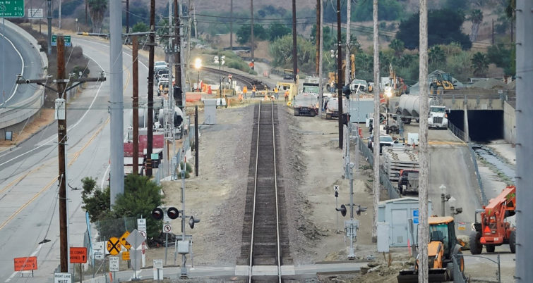
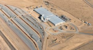
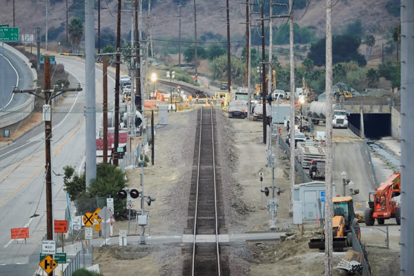
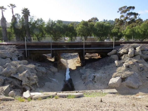
The existing LOSSAN main track in San Juan Capistrano, Calif.
The San Juan Capistrano/Laguna Niguel Passing Siding Project added 1.8 miles of new passing siding railroad track between the Laguna Niguel/Mission Viejo Metrolink Station and Trabuco Creek in San Juan Capistrano, Calif.
The passing siding track runs adjacent to the existing main track, allowing trains traveling in opposite directions to pass each other without stopping. The siding reduces delays, increases safety, and provides more reliable rail service on the Los Angeles-San Diego-San Louis Obispo (LOSSAN) rail corridor.
HNTB was the project’s civil and structural engineer of record, responsible for design of new trackwork, culvert extensions, replacement of a timber trestle with a concrete box culvert, and improvements at a grade crossing with associated roadwork. A key project goal was to achieve the necessary improvements while minimizing impacts to railroad operations. Construction of a second track with special trackwork elements and a box culvert under the existing and proposed second track would require extended work periods with no train traffic. The design team developed innovative design solutions to achieve this goal, including replacing an existing timber trestle with poor underlying soil conditions with a new concrete box culvert in a 51-hour exclusive track closure window.
Focused shutdown
The San Juan Capistrano/Laguna Niguel Passing Siding Project is located on the 351-mile LOSSAN Corridor, which extends through a six-county southern California coastal region. It is the second-busiest intercity passenger rail corridor in the U.S. and the busiest state-supported Amtrak route. Nearly 76 trains per day—comprised of passenger and freight carriers dispatched by Metrolink, including Metrolink commuter service, Amtrak’s Pacific Surfliner, and BNSF freight rail services—pass through the project area during a typical weekday. Weekend traffic is lessened due mainly to the reduced volume of passenger trains.
Given the nature of the train traffic throughout the LOSSAN Corridor, key project elements were phased with one basic strategy in mind: Minimize railroad disruptions by focusing shutdown work on a few weekends. A key project feature—replacement of the timber trestle—would require a long weekend, plus careful planning and innovation due to the extensive work involved and the tight schedule constraint coupled with challenging soil conditions.
Messy settlement
Metrolink identified the timber trestle to be nearing the end of its useful life and in need of replacement in roughly the same time period as the proposed construction of the San Juan Capistrano/Laguna Niguel Passing Siding Project. Compressible soils at the site indicated settlement would be a key consideration for any new construction over the channel bottom.
The overall watershed draining through the culvert is approximately 83 acres, including the offsite runoff from the I-5 freeway and adjacent Camino Capistrano roadway. The culvert was designed to pass the 100-year peak flow of 251 cu ft per second; however, the existing upstream and downstream connections outside the rail right-of-way are undersized. Existing wooden bents physically constrained the culvert size, so a detailed field investigation and survey were critical to determine the maximum practicable section that could be constructed as a cast-in-place option.
The existing timber trestle, more than 100 years old, showed signs of disrepair, and the approaches frequently required track maintenance to fix settlement issues. The proposed siding required the addition of two new tracks at this location, and the timber trestle did not lend itself to a compatible widening option. Considering the site geological conditions, bridge needs, channel function requirement, and compressed construction time frame, a concrete culvert option was selected. The decision was further solidified based on the culvert’s ability to spread reaction loads to underlying subgrade without requiring deep foundations. The engineering team used a single-cell box option to make the structural, geotechnical, and hydraulics work for all the design requirements. The design team provided the contractor with the option to use precast instead of cast-in-place to expedite construction.
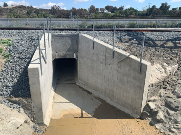
The box culvert was located at the deepest part of the channel and then backfilled to meet grades on either side and backfilled on top to accommodate the three new track sections. The box culvert was approximately 9 ft high x 8 ft wide and 60 ft long, including the wingwalls. The existing timber trestle was removed in-kind, and the treated timber piles were cut 2 ft below the lowest excavation grade.
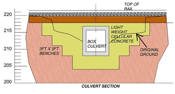
To eliminate settlements and the unacceptably long time periods involved, the design drove toward using lightweight cellular concrete (LCC) in a load-balancing approach. LCC was preferred due to its ability to be cast in place and its extremely light weight. In this approach, enough existing normal weight soils in and around the channel would be excavated so the total weight of the added LCC and the box culvert would be no greater than the existing load on the clays in the channel, creating a zero additional load condition. With this approach, rail traffic could operate on the new box culvert without long-term settlement issues.
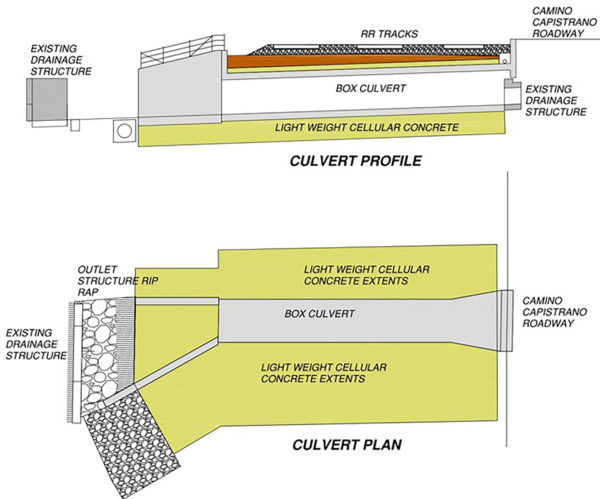
The design led to the section shown in Figure 3. The solid line (original grade) is the existing grade, and the inverted pyramid area is the LCC required for the load-balancing approach. Figure 4 shows limits of LCC in the plan and section around the box culvert.
It’s Absolute
To minimize disruption to commuter and freight rail services, complete bridge replacement was required to take place during a weekend Absolute Work Window (AWW). The project required removal of a section of mainline track, existing bridge demolition, excavation, LCC placement, and box culvert installation, all within 51 hours beginning on Friday evening with the track open to regular commuter service the following Monday morning.
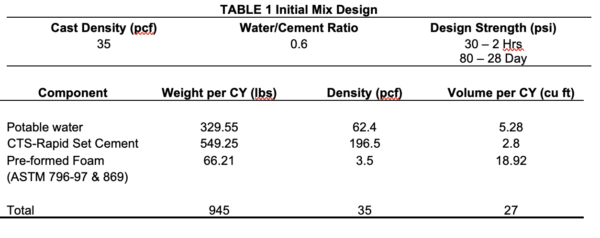
Work within the AWW required cutting and temporarily removing a length of mainline track (rail and wood ties) and ballast, removal of the timber trestle, cutting the foundation piles, excavation to make room for the design LCC section, placing the new box culvert, backfilling with LCC, and restoring grades and track. To provide maximum flexibility during construction, the contractor was given a precast concrete option for the box culvert and the LCC specification was written as a performance specification meeting select operational and design requirements. The minimum required strength was 30 psi in two hours, which provided enough strength for rail restoration on the topmost lift and to support train traffic following the AWW.
The 30 psi in two hours translated to an 80-psi strength requirement at 28 days. The mix density to meet the load-balancing requirements was 35 pcf. The maximum lift thickness was set at 5 ft, as beyond 5 ft thickness the foam bubbles in LCC crush and the mix rapidly gains density.
Prior to bid, HNTB had extensive discussions with LCC contractors to discuss the feasibility of placing such a large quantity of LCC—590 cu yd in 5-ft lifts within the weekend window. Specialty contractors noted that this would be the first application of LCC placed in such a limited time window and that rapid set cement would be an ingredient in the mix.
The key performance criteria HNTB developed with contractor input were:
Maximum cast density: 35 pcf;
Maximum pour height/lift thickness: 5 ft to prevent collapse of the foam bubbles within the mix;
Minimum compressive strength: 30 psi within two hours for each lift prior to placing the precast box culvert or subsequent lift;
Minimum compressive strength: 30 psi prior to allowing train operations;
Maximum total placing time for entire LCC volume: 10 hours;
Minimum 28-day compressive strength: 80 psi for all lifts; and
Maximum % water absorption after 120 days: 16%
Throop Lightweight Fill, Pasadena, Calif., won the contract for the LCC work. Reyes Construction, Pomona, Calif., was the general contractor. The proposed mix was a combination of rapid set cement (required for early high-strength gain), water, and foam. The initial mix design particulars are shown in Table 1.
With this initial mix design, Throop started construction trials. Contrary to expectations, due to the large amount of rapid set cement used the mix exhibited very high heat of hydration that led to delamination of field cast trial blocks.
This delamination was not acceptable, because the placed LCC started losing its shear strength forming LCC aggregate and not homogeneous solid block. With the AWW fast approaching—just 15 days away—a more robust mix was required.
Throop went about designing a new mix, ultimately proposing a mix with fly ash, a reduced quantity of the rapid set cement, chilled water, ice, and special retarders to control the heat of hydration.
In Throop’s field trials, this new mix achieved a density of less than 35 pcf, and the two-hour strength ranged between 52 psi and 56 psi, more than the required minimum. The strengths were tested using 2.97-in. x 5.4-in.-high cylinders. The reduction of the rapid set cement and addition of fly ash resolved the tendency of the mix to delaminate. Reyes then stacked 4-ft cube blocks of regular weight concrete on the LCC to simulate design loads and to demonstrate the placed LCC would support those loads when rail service resumed.
LCC was placed between Saturday and Sunday. Throop had to make several adjustments to placement operation in the field as it tackled difficult LCC behavior with rapid set cement. To resolve the LCC mix setting up in the slick lines during pumping before discharging, Throop switched to larger-diameter lines and reduced pumping distance by moving the mixer closer to the actual placement. Now once pumping started, continual pumping reduced the risk of the LCC clogging the lines. Chilled water and ice were used in the mix along with specialty retarders for all lifts to help control the heat of hydration. Although the quantity of retarders was adjusted during placement to control the heat of hydration, the total water/cement ratio was maintained.
Prior to placing each lift, Throop performed a density test on the mix. Once the trial density came out at 35 pcf, the lift placement began. During placement, Throop took density samples every 10 to 15 minutes to monitor the mix density. Cylinders also were taken during each lift to confirm strength. Based on density test results, mix ingredients were adjusted to keep the density as close as possible to the specification requirements. For all the lifts, Throop was able to maintain the density in the 35- to 38-pcf range, which was acceptable.
The precast box culvert placement occurred without issues.
As part of the contractor’s planning for the AWW, an hour-by-hour schedule was developed for the numerous construction activities that would take place during the weekend outage. The contractor was delayed a few hours due to complications with the removal of timber piles for the existing bridge structure. Otherwise, the construction activities followed the planned schedule very closely. Major construction elements during the AWW included:
Removing mainline track (panel);
Demolishing existing bridge foundation and superstructure;
Excavating for reinforced concrete box (RCB);
Placing LCC lift No. 1 and cure approximately 104 cu yd of LCC;
Grading and setting RCB and place bulkheads for additional lifts;
Placing and curing LCC lifts No. 2 (approximately 120 cu yd) and No. 3 (approximately 190 cu yd);
Reinstalling track panel; and
Surfacing, stabilizing, and destressing track.
By 4 p.m. Sunday, nearly 40 hours into the work window, the mainline track panel was placed back into position. The track was surfaced, stabilized, and destressed ready for mainline traffic by early Monday morning.
First time of many?
The bridge replacement and LCC placement were a success. The required density range of LCC was achieved and placement of 590 cu yd of LCC was completed in the 51-hour AWW as planned. In this first-time use of rapid set cement in LCC, all challenges were successfully overcome to achieve a finished LCC product that met final strength and density goals.
This article appeared in the May issue of RT&S. The authors are:
Graham Christie, P.E.,
Aamir Durrani, P.E.,
Murali Hariharan, P.E., G.E.,
and Jason Lee, P.E.
This information was first written and presented for the AREMA 2021 Virtual Conference.