Top Projects for 2026: Remarkable Feats of Railroad Engineering
Written by David C. Lester, Editor & Jennifer McLawhorn, Managing Editor
The Park Avenue Viaduct Replacement Project is one of RT&S’ Top Projects for 2026.
MTA Construction & Development
ATLANTA - Here are the Top Projects for 2026, as featured in RT&S' June 2026 issue.
We’ve written before that our annual “Top Projects” recognition and honors is one of our favorites of the year. This is because most everything associated with rail engineering is project-based and, in a phrase, is how things get done. Successful project management is a continuous process of planning and executing. Some rail engineering projects are required to repair serious damage to a rail line or its supporting infrastructure, while others are required to maintain a state of good repair, and still others are focused on new infrastructure, new business, or expansion of existing infrastructure and business.
We want to express our appreciation to everyone who submitted a project for consideration of Top Projects honors. We know that it requires enthusiasm, careful thought and writing, time, and deep understanding of a project to prepare a submission. Unfortunately, the amount of space we have in the magazine is limited, so we cannot recognize every project submitted. Nevertheless, even submissions that are not chosen are carefully read and keep our editors informed about the wide variety of projects underway at a given time.
We invite our readers to enjoy reading about our Top Projects selections to see what else is going on in the industry and, perhaps, get some ideas for planning and executing your company’s upcoming projects.
Park Avenue Viaduct Replacement Project
- Location: New York, NY, USA
- Contractor: Halmar International
- Designer: AECOM
- Owner: MTA Construction and Development and MTA Metro-North Railroad
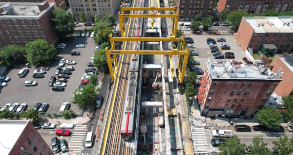
The Park Avenue Viaduct Replacement Project represents the most complex infrastructure undertaking in Metro-North Railroad’s history, addressing the urgent need to replace critical aging structures on one of the busiest commuter rail corridors in the United States. The project contains a variety of railroad infrastructure replacements and upgrades while maintaining full train service of 750 trains per day in a dense urban environment while maintaining an extremely accelerated program timeline.
The Park Avenue Viaduct Replacement Project Phase 1 and Phase 2 presented a unique combination of technical, operational, and logistical challenges. The project required replacement of 196 bridge structures, all while maintaining all rail service for 230,000 customer per day. One of the primary challenges was executing large-scale structural replacement within limited weekend outage windows while maintaining weekday operations. On the weekends, only 2 of the 4 tracks could be taken out of service, requiring the remaining tracks to carry full weekend service of over 400 trains per day without disruption. Conventional construction methods would have requiredapproximately 98 weekend outages; however, through innovative means, the project replaced all 196 bridges in just 28 weekends.
The constrained urban environment further complicated the work, with limited access, restricted staging areas, real estate relocations, and the need to minimize impacts to the surrounding community. To overcome these challenges, the project utilized three custom built gantry systems capable of lifting and placing large, prefabricated bridge units with precision, eliminating the need for traditional crane operations and accelerating weekend production. This was paired with the implementation of intertrack containment, which allowed construction activities to safely occur adjacent to active tracks. Coordination between the designer, contractor, and railroad was critical to success. The team developed highly detailed sequencing plans, allowing multiple activities to occur within the same outage windows, significantly improving efficiency. These combined strategies enabled Phase 1 of the project to be completed in 39 months—21 months ahead of schedule—while maintaining safety, minimizing service disruptions, and delivering a critical infrastructure upgrade. With the addition of Phase 2 as a change order, the project is expected to be completed 60 months sooner than originally planned due to the efficiencies and accelerated design-build schedule.
California High-Speed Rail (CAHSR) Rail Material Depot
- Location: Wasco, Calif.
- Contractor: Ragner Benson
- Designer: RailPros
- Owner: BNSF Railway & California High-Speed Rail
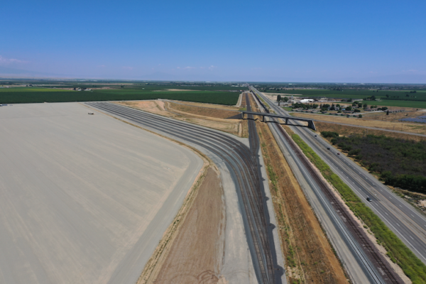
The California High Speed Rail (CAHSR) Rail Material Depot, also referred to as the Southern Railhead, was constructed as a major rail facility in Wasco, Calif., to support the delivery, staging, and distribution of track, signal, and overhead contact system materials for the California High Speed Rail program. For the designer, key challenges on this complex, multi-year project included the necessity of coordinating with multiple stakeholders while simultaneously managing an aggressive schedule toward completion. The project team coordinated with both the Class I project owner and the Passenger/Transit project owner. The facility creates a direct rail connection between the BNSF mainline and the CAHSR construction footprint, allowing material trains to arrive by rail for future usage. The project included construction of more than 45,000’ of new rail infrastructure, which included a new nearly 12,000’ BNSF siding. The completed track layout includes 13 total turnouts and two new control points, establishing the operating infrastructure required to receive trains from the BNSF mainline and route materials into the yard.
Environmental compliance was a key challenge for the contractor on this project – the project’s location required extensive efforts and effective coordination to maintaincompliance. Site development required clearing approximately 134 acres of former orchard area. Removed orchard trees were chipped, with material sent to a recycling center for repurposing and a small portion spread on site where suitable for ground cover. During tree removal, night work was implemented to protect Swainson Hawks. There were also restricted work areas for nesting Owls as well as extensive biological species monitoring and trapping to allow construction activities to continue in certain areas.
Another challenge was the sheer size of the project – the scale of the Southern Railhead extended well beyond track construction. The project included installation of nearly 138,000 cubic yards of Caltrans Class 2 aggregate base, almost 8,000 linear feet of underground electrical conduct, and approximately 10,000 linear feet of fencing. Around 134 acres of former orchard area were cleared to prepare the site for rail yard, laydown, drainage, and access improvements. The project also included construction of three retention basins, requiring movement of nearly 84,000 cubic yards of earth, to provide drainage capacity for the completed facility and future High Speed Rail construction operations.
During construction, teams coordinated extensively with regulatory stakeholders, including the California State Water Resources Board and the California Department of Fish and Wildlife (CDFW). Field activities were performed under permit requirements that included biological oversight, environmental monitoring, and implementation of an extensive Stormwater Pollution Prevention Plan (SWPPP). These requirements influenced site access, sequencing, grading, drainage work, and daily field execution. Due to the active railroad interface, the vast construction footprint, and the volume of civil and track construction completed, another concern was safety – but the teams involved achieved outstanding safety performance. The work was completed without a single injury across tens of thousands of work hours performed by BNSF, Ragner Benson, RailPros, and other project partners.
Franconia-Springfield Bypass CMGC Project
- Location: Springfield, Va.
- Contractor: Flatiron–Herzog Joint Venture
- Designer: Parsons
- Owner: Virginia Passenger Rail Authority (VPRA)
The Franconia-Springfield Bypass CMGC Project requires active track and bridge construction in a narrow corridor that has limited site access and extensive utility relocation requirements. The joint venture of FlatironDragados Constructors and Herzog Contracting Corp. (Flatiron-Herzog) is collaborating with the Virginia Passenger Rail Authority (VPRA) to build a 0.6-mile flyover bypass bridge with one new mainline track, allowing passenger trains to pass over two existing CSXT mainline freight tracks. The overall bridge structure, including retained fill approaches, spans approximately 5,000 feet and reaches a height of 36.6 feet. The bridge crosses over existing CSXT tracks 2 and 3 and includes 248 CIDH foundations, 34 bents, and 15 units/spans (including two caps and six hammerhead columns per unit). In total, the project corridor extends 1.8 miles with significant clearing, grubbing, and earthwork, 2,700 feet of retaining wall structures, drainage structures, track shifts, 8,000 feet of new mainline ballasted track tying into the at-grade mainline, and wayside signal improvements. The project corridor serves as a critical link supporting passenger, commuter, and freight rail operations between Washington, D.C. and Richmond, VA. Construction is performed in an active track environment around 80+ daily CSXT, Amtrak, and Virginia Railway Authority (VRE) train movements.
Following preconstruction NTP, the project team analyzed CSXT, Amtrak, and VRE train schedules and identified a significant schedule risk. Work crews were limited to four hours of daily production due to frequent train movements requiring crews to clear the foul zone 80+ times per day. Flatiron-Herzog proposed an innovative shoofly solution to mitigate this risk and increase productivity. The project team developed white papers and provided detailed specifications to the owner and designer to demonstrate the benefits of two shooflies — a south shoofly and a north shoofly — to shift the active tracks away from the work zone. The shoofly concept was approved as an early works package at the 60% design milestones. This innovation eliminates the need for shoring and separates live rail operations from construction activities, creating substantial work windows outside the 25-foot foul zone and improving worksite safety as the project transitions to Phase 2 construction. The shoofly strategy provides $34M in cost savings and accelerates the schedule by eight months.
The Flatiron-Herzog team has begun cutting and filling for wall construction on the south shoofly, as well as cutting the initial benches for two soil nail walls (Wall 5 and 4a) and drilling soil nails on Wall 5. Limited site access created significant logistical challenges for moving heavy equipment to the site and completing construction activities in a narrow right of way (ROW) with a steep slope and drop-off. At one pinch point, the project team only has 12- to 15 feet of clearance for substructure work. Flatiron-Herzog developed one solution with the construction of four wire walls, two at the entrances and two adjacent to the property line. These wire walls will serve as temporary structures to improve access for setting up and operating cranes and other heavy equipment.
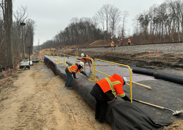
BERX Emergency Slope Stabilization Project
- Location: Deerfield, Mass.
- Contractor: All States Material Group
- Designer: Colliers Engineering & Design
- Owner: Berkshire & Eastern Railroad (Subsidiary of Genesee & Wyoming)
The Berkshire & Eastern Railroad (BERX) undertook an emergency slope stabilization project in Deerfield, Mass., after a slope failure threatened active rail operations. The project had to be designed and permitted under an accelerated schedule while maintaining compliance with state and federal environmental requirements.
Early coordination, flexible design, and proactive permitting strategy helped the team navigate a complex regulatory process under emergency conditions. Permitting was identified as the project’s critical path, and agencies including MassDEP, USACE, and MassWildlife were engaged early to provide feedback as the design progressed. The team aligned design milestones with permitting needs, which allowed documentation, site visits, and agency coordination to happen in parallel.
Lessons learned include the importance of collecting early field data to confirm regulatory limits, maintaining weekly communication with agencies to address shifting expectations, and integrating contractor input to keep the project buildable and on schedule.
Birmingham 14th St Junction Project
- Location: Birmingham, Ala.
- Contractor: Norfolk Southern
- Designer: Norfolk Southern
- Owner: Norfolk Southern
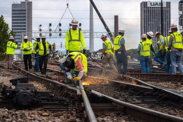
Ed Boyle, Vice President of Engineering at Norfolk Southern said of this project: “Reconfiguring and replacing the complex 14th Street Junction required close alignment between two Class I railroads at one of the Southeast’s most important freight intersections. Our engineering teams focused on replacing maintenance‑intensive components, enabling higher speeds, and executing the work while protecting ongoing operations. The result is a safer, faster, and more reliable interlocking that strengthens our network for the long term.”
The primary construction challenge was delivering complex track and signal upgrades at one of the Southeast’s busiest interlockings while keeping rail traffic moving. The Birmingham 14th Street Junction supports approximately 70 trains per day on heavy tonnage mainlines, leaving virtually no tolerance for extended outages or execution risk. Experienced railroaders from Norfolk Southern and CSX completed the work within tightly controlled windows while maintaining safety and service reliability. To minimize operational disruption, construction was sequenced across five phases, each meticulously planned to allow continuous train movements while progressively transforming the interlocking. This approach required precise coordination of labor, equipment, and materials, along with close synchronization between track and signal crews.
The most demanding challenge came during the final phase, when 140 railroaders completed the most disruptive work within a 48-hour outage. Months of advance planning enabled extensive pre-staging of materials and disciplined, around the clock execution. Crews removed six legacy movable point frogs and installed new turnouts, switches, signals, and prefabricated track panels, followed immediately by testing and commissioning. All work had to be completed safely and on schedule to restore full mainline operations.
From a design standpoint, the challenge was reconfiguring a legacy interlocking that had constrained operations for decades while meeting the needs of two independently operated Class I railroads. Norfolk Southern Engineering, working closely with CSX Engineering, developed a solution to address chronic speed restrictions, maintenance issues, and operational conflicts at a critical shared junction. The design required balancing differing engineering standards, operating priorities, and future capacity needs, while ensuring constructability within an active mainline environment. Key decisions included replacing six movable point frogs with standard turnouts to improve reliability and reduce long term maintenance, while enabling significantly higher operating speeds. The final design integrated 13 new signals, 17 switches, and more than 300 feet of new track panels within a constrained footprint. Development extended over several years as both railroads aligned on a configuration that improved throughput, increased speeds, and ensured safe, efficient operations through one of the region’s most critical interlockings.
Close collaboration between design and construction teams was essential to move a complex plan from concept to execution. A primary shared issue was sequencing: the design had to be built in five phases to maintain service continuity, requiring detailed coordination to ensure each stage supported the final configuration. Constructability and material staging were also critical. The 48-hour final phase demanded that all components — signals, switches, turnouts, and prefabricated track panels — be designed, staged, and ready for rapid installation. Designers and field teams worked together to refine installation details, particularly around removing maintenance-intensive movable point frogs and replacing them with standard turnouts within strict time constraints. Signal integration required similarly close alignment. Track and signal installations had to be coordinated with testing and cutover activities to allow safe, timely commissioning. Across all phases, both teams worked jointly to ensure safety, operational continuity, and long-term performance objectives were fully met.
CSXT Howard Street Tunnel Project
- Location: Baltimore, Md.
- Contractor: Skanska-Fay JV
- Designer: Hatch
- Owner: CSXT
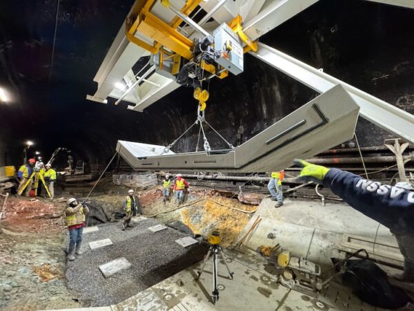
Brandon Knapp, P.E., Senior Director of Mid-Atlantic Construction for CSX Transportation said of this project: “The Howard Street Tunnel Project demanded a modern solution to a 19th‑century structure. The project was delivered safely and precisely under an accelerated schedule in one of the most constrained environments in the railway industry.”
The primary challenges for the contractor on this project to reconstruct a 130-year-old brick lined tunnel were:
- Track outage window / schedule pressure: The tunnel was closed to train traffic for eight months. The contractor worked 24/7 to maintain the reopening date schedule.
- Existing conditions + limited unsupported excavation lengths: Safe progress depended on tight excavation limits, essential dewatering, and continuous instrumentation/monitoring to control ground/tunnel movement and protect adjacent infrastructure.
- Staging and access constraints: Getting materials in/out required a long rail access route, limited portal access, and a logistics plan moving deliveries from the east and spoils to the west.
- Limited space + need for specialized equipment/means & methods: Confined tunnel geometry forced use of custom and highly specialized equipment (including a purpose-built gantry to set 10‑ton precast segments) and made concrete placement at the face a key challenge until they changed the load-path approach.
- Uncertain existing conditions: Risk from undocumented utilities, unknown structural elements, and variable subsurface conditions that had to be managed during execution.
The primary challenges for the designer on this project were:
- Accurately defining existing geometry and constraints: Building a reliable “as-is” tunnel model from record drawings plus detailed survey/LiDAR to drive clearance and track profile decisions.
- Designing to fit outage/constructability windows: All concepts had to be buildable within prescribed outage strategies (and sequencing/durations), which strongly constrained what could be designed.
- Working in a dense urban/utility environment with groundwater: Proximity to major infrastructure/utilities plus groundwater required careful evaluation—especially where invert work and dewatering would be needed.
- Maintaining structural stability and load paths during modifications: Ensuring continuity of load paths during each phase of construction, particularly when existing tunnel elements were altered or temporarily removed (and avoiding roof notching to reduce risk).
- Severely limited access/work from inside the tunnel: Site access limitations meant the design had to assume construction largely from within the tunnel, driving “means-and-methods-aware” detailing.
- Highly variable tunnel geometry/structure/ground conditions: Different sections (mined, cut-and-cover, concrete box) and varying conditions required customized, segment-specific solutions rather than one standard detail.
- Balancing clearance strategy tradeoffs: Prefer track lowering for cost/schedule/risk, but in many locations, it wasn’t enough—forcing invert replacement and tightly controlled excavation/dewatering parameters.
As this was a Progressive Design-Build project, the designer and contractor worked hand in hand along with the owner, CSX. Some of the key issues that the designer and contractor had to work out together were:
- Construction sequencing vs. structural stability: Agreeing on an invert demo/excavation/replacement cycle that maintained continuous load paths and avoided damaging the existing brick/masonry liner—especially where elements were temporarily removed.
- Allowable unsupported excavation limits: Converting the designer’s 3D geostructural modeling outputs into field-usable excavation length/depth limits and validating them with instrumentation/monitoring so production could move without traditional support of excavation.
- Groundwater control and dewatering approach: Coordinating where/when localized dewatering was required(permeable soils, deeper notches/replacements), how much drawdown was needed, and how dewatering tied into the daily production cycle.
- Clearance strategy and “no roof notching” constraint: Aligning the track profile / clearance envelope needs with the constructible solution set (i.e., track lowering + invert notching/replacement only) and the impacts on means/methods.
- Precast invert system constructability: Finalizing PCIS/PCIU details around segment sizing/weight (10-ton pieces), tolerances, setting blocks/leveling pads, bolting, contact grouting, and how those steps fit the outage window and production rates.
- Critical-path operations and productivity: Working through the original in-tunnel concrete batching/placement at the workface challenge and the shift to a temporary jacking system to complete load paths, removing concrete placement from the critical path and improving cycle time.
- Logistics and access-driven design decisions: Coordinating design assumptions with the reality of a single work front, material delivery from the east by rail, and spoils removal to the west, including the need for the purpose-built segment gantry and specialized equipment to avoid clashes in low clearance areas.
Kansas City Streetcar Main Street Extension
- Location: Kansas City, Mo.
- Contractor: Kansas City Streetcar Constructors (a joint venture of Herzog Contracting Group and Stacy Witbeck)
- Designer: HDR
- Owner: Kansas City, Mo.
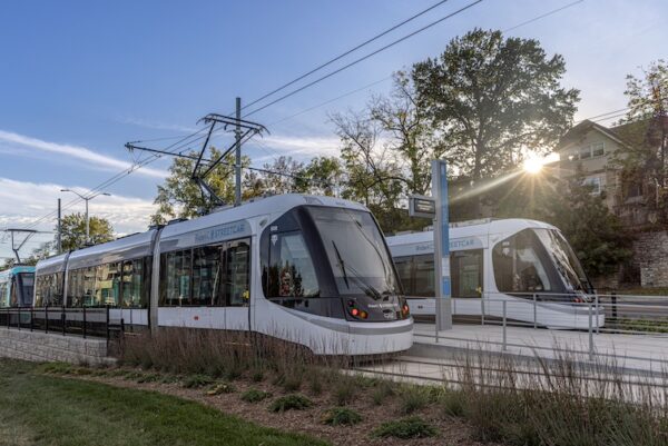
In 2016, the City of Kansas City opened the Downtown Streetcar line, a 2.2-mile system through the heart of downtown, with free ridership to and from all 16 stops. Upon completion of the Downtown Line, the corridor quickly cemented its status as a major hub for downtown residents, visitors, commuters, and developers. This convenient transportation option has become an iconic part of downtown.
The $352 million Main Street Extension adds 3.5 route-miles of new streetcar service, starting at Union Station and ending at the University of Missouri-Kansas City (UMKC). The expanded route will include 15 new stops, improved pedestrian access and public space, and eight new vehicles, evolving into a true spine in the regional transit system. The fare-free, zero-emission transit service will connect dense neighborhoods, busy business districts, world-class cultural institutions, and vibrant academic communities within Kansas City.
The Main Street Extension continues the four themes that propelled the Downtown Line: connect, develop, thrive, and sustain. It provides mobility and connectivity, economic development and growth, community amenities and improved livability, and sustainability. It expands mobility choices for the area; adds new connection points for regional transit; improves accessibility; provides efficient, reliable, and safe transit; encourages development of underutilized and vacant property; supports existing residential and commercial activity; and enhances the desirability of the corridor for employment and residential growth. In contrast to the Downtown line, which passes through the region’s central business district on historic streets, the Main Street Extension passes through the gentle density of Midtown Kansas City on a wider thoroughfare that integrates dedicated transit lanes. The project also includes a new operations control center and expands the existing maintenance yard. New signature stops at the Plaza Transit Center and University of Missouri-Kansas City integrate the project into the local community.
The project team overcame significant challenges, including designing the extension through a developed, urban landscape, with faster speeds and more hills than the starter line; hazardous materials; historical resources; floodplains; and coordinating with agencies, governments, partners, and stakeholders. The result is one of the most ambitious transit expansions in recent local history. The project will improve the quality of transit and enhance opportunities for Kansas Citians for decades to come.
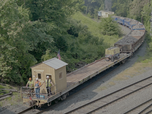
North Sioux City Bridge
- Location: North Sioux City, S.D.
- Contractor: Ames Construction, Inc.
- Designer: HNTB
- Owner: BNSF Railway
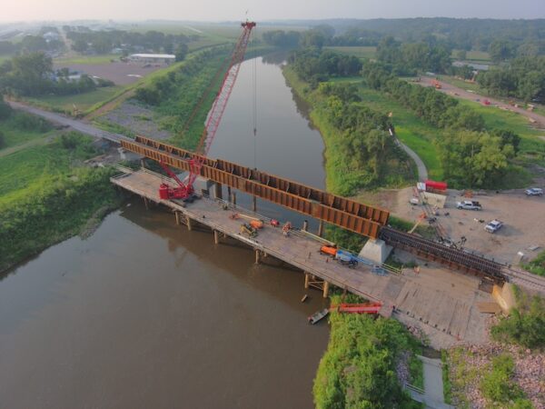
BNSF Bridge 518.90, located on the Iowa–South Dakota border at North Sioux City, experienced severe scour in June 2024 following heavy rainfall and historic flooding that caused widespread damage across the area. At the request of BNSF, Ames Construction mobilized to the site within days of the event. Demolition was completed by mid-September 2024, and construction of the replacement bridge began in February 2025. For Improved resiliency, BNSF opted to utilize a new drilled shaft center pier and rehabilitation of an existing pier on the South Dakota side of the river and replaced two existing through truss spans with similar length through-plate girder (TPG) spans.
A primary challenge of the project was obtaining the required permit approvals for working in the levee zone. The bridge was designed and awarded quickly, but the construction start depended on multiple approvals from public agencies. The bridge needed to be reopened by August 1, 2025 in order to serve the agricultural customers who rely on this route during harvest season. To meet this deadline, multiple phases of work were performed using double shifts.
Condensing the schedule was a continuing goal of the project. To offset other delays, as well as open the bridge for rail traffic operated by BNSF’s shortline partner Dakota and Iowa Railroad (DAIR), Ames was asked to accelerate the schedule by nearly two months. This required double shifts for multiple activities, including the construction of the temporary work trestle and the erection of the through-plate girder (TPG) spans. The double shifts further increased the project’s complexity by adding night work at heights over the river. another challenge involved rehabilitation of the existing western pier. The exterior concrete of the pier varied in age due to multiple updates over the years, while the interior was filled with crushed limestone rubble. The original design called for almost 300 dowels to be drilled and epoxied into the existing pier. Concerned that excessive drilling would cause the rubble-filled pier to be compromised, Ames collaborated with BNSF and HNTB to develop an alternative solution: a post-stressed pier cap that clamped onto the top of the existing pier.
The footprint could not be increased to retrofit the pier for permit compliance within the levee zone. The solution was to design a new pier cap that clamped onto the existing pier using post-tension members. The existing pier was cut with concrete wire saw to create a key in the center of the cap. The cap was then placed and tensioned, securing it on the existing pier.
Another challenge involved the drilled shafts. The original design of the drilled shafts was based on soil borings collected on the shoreline, which showed bedrock 20 feet higher than what was discovered after the temporary work trestle was built and the borings could be performed at the location of the drilled shafts in the river. Working with HNTB, Ames was able to use materials on-hand for drilled shaft reinforcement, as the vertical bars were #18 and sourcing more #18 material would require a long lead time. The designer modified the rebar to use what was on-hand, and Ames’ drilled shaft subcontractor was able to procure additional 20-by-8.5-foot casing within weeks to splice onto the 90-foot casings that were previously ordered. Even with the mid-project revisions, Ames was able to keep the construction of the drilled shafts on schedule.
The result of schedule compression and working within the required parameters of the levee zone was an overall success. The bridge re-opened for rail traffic prior to harvest season, which then allowed crews to remove the temporary work trestle and restore the levee area.
Media
RELATED ARTICLES